PWM Servo Motors
PWM servo motors are compact rotary actuators commanded by a standard pulse-width signal — usually 1.0–2.0 ms at 50 Hz — where pulse width maps directly to shaft angle. The servo closes its own position loop internally with a potentiometer or magnetic encoder, so the controller only needs one signal wire per axis.
What a PWM servo is good for
- RC models, pan-tilt camera mounts and gimbals
- 3D-printed robot arms and grippers below 20 kg·cm
- Lab fixtures, dampers and light valve actuation
- Prototyping where an Arduino or PLC already outputs PWM
Typical PWM servo specifications
| Command signal | 50–333 Hz PWM, 1.0–2.0 ms (0.5–2.5 ms extended range) |
| Supply voltage | 4.8–8.4 V DC (hobby) / 12–24 V DC (industrial) |
| Torque range | 1–70 kg·cm (0.1–6.9 N·m) |
| Feedback | Internal potentiometer or magnetic encoder; no bus feedback |
| Wiring | 3-wire: signal, V+, GND |
| Control mode | Position (angle) only |
How to size a PWM servo
Size from the load, not from the datasheet headline. Required torque ≈ load (kg) × arm length (cm) × 1.5 safety factor. A 1 kg payload on a 10 cm horn needs roughly 15 kg·cm, which is why most small arms sit in the 20–60 kg·cm band.
FAQ
PWM servo or serial bus servo?
Use PWM when you need one axis, one direction of command and the lowest cost. Move to RS-485, CAN or TTL when you need position feedback, many axes on one cable, or fault reporting.
Can a PLC drive a PWM servo?
Yes, if the PLC has a pulse output module that can hold 1.0–2.0 ms pulses at 50 Hz. Most compact PLCs need a dedicated pulse module.
Why does my PWM servo jitter?
Usually an unstable supply or a shared ground with a noisy load. Give the servo its own 5–6 V rail with at least 1 A of headroom per unit.
Comparing interfaces? See TTL serial servo motors or browse servo motors under 20 kg·cm.
Showing 1–12 of 40 results
-
130–400 kg·cm Servo Motors
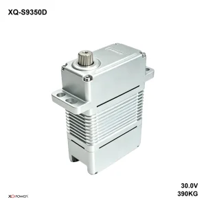
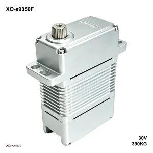
XQ-S9350F 390kg (38.2 N·m) 30V High-Torque Brushless Industrial Servo
Read more -
130–400 kg·cm Servo Motors
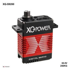
Industrial Brushless Servo S9200D 250kg (24.5 N·m) 30V 405g PWM
Read more -
60–130 kg·cm Servo Motors
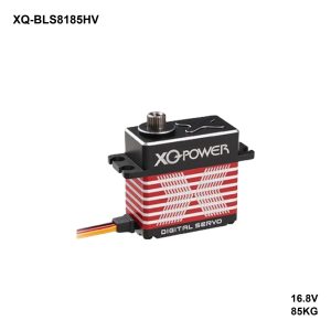
Heavy Duty Brushless Servo BLS8185HV 85kg (8.3 N·m) 16.8V 92g PWM
Read more