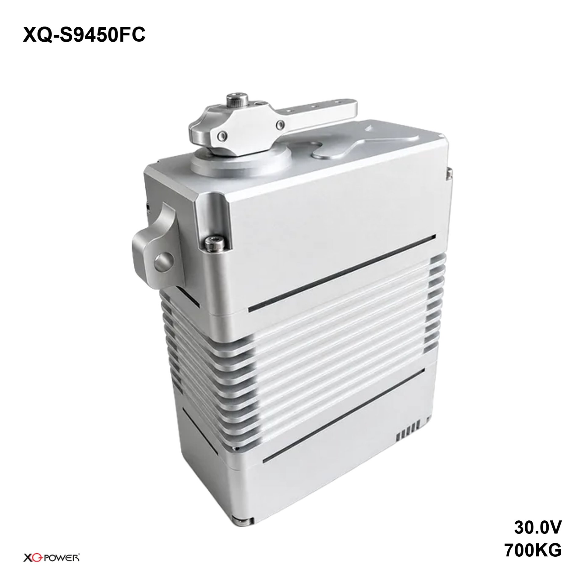
XQ-S9450FC — 700 kg·cm (68.6 N·m) as a CAN node, for two heavy axes that have to stay in step A brushless motor drives a steel train onto a 25T, φ11.98 mm output in eight ball bearings, inside a 100 × 50 × 97 mm machined aluminium case at 895 g, with the mounting ears on the long sides so the unit bolts flat to a plate. The input stage is a CAN node, and the master decides when each frame leaves.
The unit is rated 560 kg·cm on 24 V, 650 kg·cm on 28 V and 700 kg·cm on 30 V, with speed and current published at each rail. Inspection sheet X9_9450.05, dated 2025-02-22, is the source for all of it.
| Peak stall torque700 kg·cmat 30 V · 9721.2 oz-in · 68.6 N·m | Speed0.21 s/60°at 30 V · 0.30 s at 24 V | Supply24–30 Vthree published points |
| ControlCANCAN bus · 360° across 1000–2000 µs | Envelope100 × 50 × 97 mm122.7 mm across the ears · 25T-φ11.98 | Mass895 g8 ball bearings · no mechanical stop |
Is the XQ-S9450FC the right servo for your joint?
Two axes at 700 kg·cm on one machine are usually tied to each other: a pair of arms holding a platen, a gantry with two driven ends. On a bus the master sends both frames and the arbitration identifier decides which one waits. A few milliseconds of skew at this torque twists the structure that joins them.
The mechanics are the side-mount parts: eight bearings, φ11.98 mm output, 122.7 mm ear spacing, no stop. Travel is 360° across 1000–2000 µs, and the limit field at 3-4 is blank, so the machine owns the ends of the move.
Specify this unit when
- The machine runs a CAN bus and the master addresses nodes
- Two heavy axes must hold a relationship inside a bounded window
- The joint bolts to a plate with the output facing out
- The supply can hold 24–30 V at 22.5 A
- The move needs the better part of a full turn
Specify a different unit when
- The controller has no CAN port or gateway
- The axis depends on the servo for its end positions
- The supply sags below 24 V under load
- The bay cannot take 100 × 50 mm of case and 122.7 mm across the ears
- The joint needs more than 700 kg·cm
Torque and speed at 24, 28 and 30 Volts
The same locked-shaft points as the pulse and Modbus builds of this case, on the same rails. The bus changes when the command arrives, and it changes nothing in this table.
| Supply | Peak stall torque | No-load speed | No-load current | Stall current |
|---|---|---|---|---|
| 24 V | 560.0 kg·cm | 0.30 s/60° | 400 mA | 18 A |
| 28 V | 650.0 kg·cm | 0.25 s/60° | 430 mA | 21 A |
| 30 V | 700.0 kg·cm | 0.21 s/60° | 450 mA | 22.5 A |
700 kg·cm at 30 V with 0.21 s per 60°, 650 kg·cm at 28 V and 560 kg·cm at 24 V. The stall column runs 18, 21 and 22.5 A across those rails, and on a two-axis machine that figure doubles before anything else is counted.
No-load current is 400 to 450 mA. The gap between that and 22.5 A is the whole reason the wiring has to be planned: the joint spends most of its life drawing the small number and is sized on the large one.
Fit: envelope, spline and mass
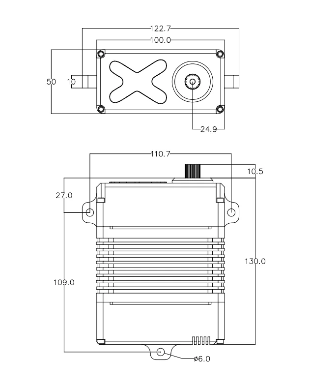
100 × 50 × 97 mm, 122.7 mm across the ears, 130.0 mm overall height with Ø6.0 holes on 15 mm ears. The ears are on the long sides, so the plate takes the moment: 700 kg·cm wants thickness and a rib behind it.
25T at φ11.98 mm with a metal arm supplied. The spline carries the full torque, and at this size the mating arm has to be cut to the spline.
895 g. On a static structure that is a mounting load; on a moving axis it is mass the drive accelerates. Either way the plate has to carry it without flexing.
Drive, current and heat
22.5 A at stall on 30 V, 450 mA at no load. The gear train carries the torque and the motor stays small, so the current is a wiring and supply question, and the drop along the run is what moves a joint from the 30 V column into the 28 V one.
Dead band 3 µs, neutral 1500 µs, window 500–2500 µs, all customizable. On the bus these are the resolution and the zero point of the position value, so they belong in the commissioning notes with the node identifier.
Fins on the long faces and the drive mounted against them. 22.5 A is a real heat load: section 2-2 puts the operating limit at 60 ℃, and the case that reaches it first is the one holding torque without moving.
Eight bearings on the output, the most in any frame below 1000 kg·cm. That is what keeps the shaft from deflecting at 700 kg·cm and what lets the arm run without support.
Sealing and environment
Section 3-11 records splash resistance as Yes on a machined aluminium case with sealed joint faces. A higher water-protection grade is built to order, with class and test standard agreed at order stage.
The J30J-15TJL connector is outside the sealed volume and carries the heavy gauge wires. Keep the plug dry or seal it to the same standard, and route the harness down and away from the entry.
−30 ℃ to 60 ℃ operating and −30 ℃ to 70 ℃ storage. The upper limit arrives faster on a joint holding a load stationary, because a sealed case cools through its fins and nothing else.
Full specification
The complete sheet for the XQ-S9450FC, in the order it appears on inspection document X9_9450.05, dated 2025-02-22: measured figures throughout, and where we have none the row says so.
| Model | XQ-S9450FC |
| Peak stall torque (SI) | 68.6 N·m at 30 V |
| Voltage range | 24–30 V |
| Control interface | CAN bus |
| Amplifier | Digital controller |
| Rotating direction | CCW (1000–2000 µs), customizable |
| Angle of limit | None, no mechanical stop |
| Motor | Brushless |
| Gear train | Steel |
| Bearing system | 8 ball bearings |
| Output spline | 25T, φ11.98 mm |
| Horn supplied | Metal arm supplied |
| Case | Aluminium CNC, all-metal case |
| Dimensions | 100 × 50 × 97 mm |
| Weight | 895 g |
| Cable length | J30J-15TJL connector, purchased separately |
| Operating temperature | −30 ℃ to 60 ℃ |
| Storage temperature | −30 ℃ to 70 ℃ |
| Sealing | Splash-proof · higher water-protection grade built to order |
| Specification revision | X9_9450.05, dated 2025-02-22 |
Download the XQ-S9450FC datasheet (PDF)
The inspection sheet for this model, including the dimensional drawing and the control-signal table, is available as a PDF.
|
XQ-S9450FC inspection specification Revision X9_9450.05 · dated 2025-02-22 · PDF |
Download PDF |
If you need the drawing in DWG, a STEP model, or the control-signal table as a separate sheet, tell us which format your CAD system uses and we will send that instead.
Variants, samples and OEM work
The pulse build is S9450F, the Modbus build RS9450FMB and the TTL build S9450FTTL. The base-mount version of the same machine is S9450D.
Four input stages are offered on this case: pulse, CAN, RS485 Modbus and TTL. Bracket, arm and 360° travel are common to all four, so the interface is a line on the quotation.
For OEM and ODM work on the XQ-S9450FC we start from five numbers: the torque you need at your speed, the supply you actually run, the interface your controller speaks, the envelope the joint allows, and the duty cycle. Send those and we answer one of three ways — the XQ-S9450FC covers it as stock at 700 kg·cm, a build of the same 100 × 50 × 97 mm frame does, or the axis needs a different frame. Send the XQ-S9450FC numbers to the engineering team.
Quick facts and cross-reference
The rows below are what to quote for the XQ-S9450FC: 700 kg·cm (68.6 N·m) on 24–30 V with CAN input, plus the two makes buyers usually weigh it against.
| Model | XQ-S9450FC |
| Peak stall torque | 700 kg·cm · 68.6 N·m at 30 V |
| Voltage range | 24–30 V |
| Control interface | CAN bus |
| Speed | 0.21 s/60° |
| Mass / envelope | 895 g · 100 × 50 × 97 mm |
| Also described as | CAN bus servo, CAN actuator, CANopen servo, robot joint actuator |
Buyers often arrive here from a CubeMars AK series or a MyActuator RMD-X series, which are built around 24-48 V robot-platform rails as integrated actuators; the XQ-S9450FC is 700 kg·cm (68.6 N·m) on 24–30 V, so put the two on the same rail and in the same unit before comparing torque.
| Cross-reference | CubeMars AK series, MyActuator RMD-X series |
| Their typical rail | built around 24-48 V robot-platform rails as integrated actuators |
| This model | 700 kg·cm (68.6 N·m) on 24–30 V, CAN input |
FAQ
How do I hold two 700 kg·cm axes in step?
Put both on the bus and let arbitration carry the priority. The identifier of the frame that must arrive first is set lower, the master schedules the pair, and the joint that can wait goes second. Baud rate, identifiers and frame layout are agreed at order stage and documented in the protocol note.
What current does the machine need for two of these?
45 A at 30 V if both can stall together, plus 450 mA each at no load. That is the number for the supply and the contactor, and it is why the pair usually gets its own feed taken from the pack.
Does the sheet header torque apply?
The header carries 450 kg·cm from an earlier rating of this frame. Rows 4-4, 4-8 and 4-12 give 560, 650 and 700 kg·cm at 24, 28 and 30 V, and this page quotes the measured rows.
Is there a stop inside?
No. Section 3-4 reads No Limit and 5-5 gives 360° across the 1000–2000 µs span. At 700 kg·cm the machine must own its limits, because the servo will drive through a soft stop.
Is a lead included?
No. The case carries a J30J-15TJL connector and the mating lead is a separate purchase. Tell us the run length and the gauge the installation needs and the harness is quoted with the servo.
Can I mount it on its base instead?
Yes. The base-mount version of the same machine is S9450D: same 100 × 50 × 97 mm case, same 895 g, same eight bearings and same output. The difference is where the ears are.
Is the XQ-S9450FC a drop-in replacement for a CubeMars AK series?
No. The CubeMars AK series runs on a different rail and a different frame, while the XQ-S9450FC is 700 kg·cm (68.6 N·m) on 24–30 V with CAN input, so a swap means checking voltage, envelope and travel first. Send the rail and envelope your machine runs and we will say whether the XQ-S9450FC frame fits.
What should I compare before choosing between the XQ-S9450FC and a MyActuator RMD-X series?
Four numbers decide between the XQ-S9450FC and a MyActuator RMD-X series: peak stall torque in N·m, the rail you actually run, stall current, and whether your controller speaks CAN. The XQ-S9450FC publishes 700 kg·cm (68.6 N·m) on 24–30 V; put the MyActuator RMD-X series on that same rail and in the same unit before you compare the two.