
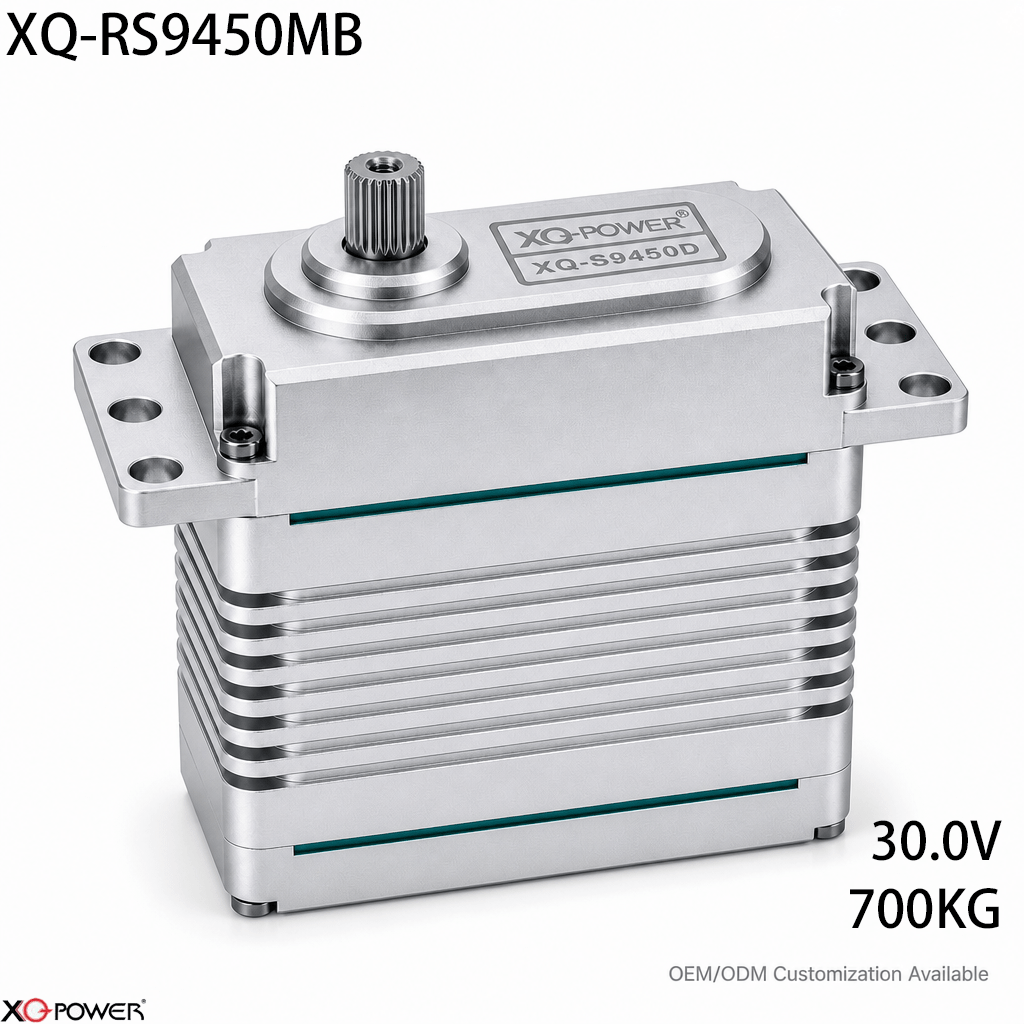
A high-torque actuator becomes much more useful when the automation system can command it, identify it, and read its operating data through the same industrial control architecture used by the rest of the machine. The XQ-RS9450MB is designed around that requirement: the product page presents it as a 700kg-class MODBUS-RTU industrial brushless actuator for integration with PLCs, HMIs, and SCADA systems.
The published reference point is 700kg.cm (9,721oz-in) at 30V with an operating speed of 0.21 sec/60°. The product information also identifies a 24–30V voltage range, a brushless motor, a toughened steel gear train, eight ball bearings, RS485-based MODBUS-RTU communication, and feedback for absolute position, torque load, and internal temperature.
This article is intentionally different from a catalogue-style product description. It focuses on the questions a controls engineer, machine builder, or OEM integrator should answer before placing a 700kg actuator inside a PLC-controlled motion cell.
Decide whether MODBUS-RTU fits the control cabinet
The first question is not simply whether the actuator has high torque. It is whether the actuator can fit the machine’s existing control model.
MODBUS-RTU can be a practical choice when the system already includes a PLC, HMI, or SCADA layer that needs to exchange commands and operating data with field devices. For the RS9450MB, the integration review should begin with these items:
- the PLC or industrial controller’s available RS485 interface;
- the required MODBUS-RTU function codes and register map;
- the number of actuators and other serial devices on the network;
- the expected command and feedback cycle;
- the addressing and commissioning procedure;
- the way position, torque load, and internal temperature data will be displayed or logged.
The product page states that the RS9450MB supports standard MODBUS-RTU function codes for reading absolute position, torque load, and internal temperature. Before a production build, confirm the exact register definitions, data format, scaling, writable parameters, and fault behavior in the applicable technical documentation.
Map the actuator into the PLC sequence
A PLC-controlled actuator should be treated as a defined motion device inside the machine sequence, not as an isolated motor that receives a command whenever an operator presses a button.
A robust sequence normally answers five questions:
- How is the node identified? — Assign a clear device address and document it in the electrical drawings and PLC project.
- What is the safe startup state? — Define what the actuator should do after power-up, controller restart, or communication recovery.
- What confirms that a command was accepted? — Use the available feedback and status information rather than assuming that a transmitted command equals completed motion.
- What stops the motion? — Define travel limits, machine interlocks, and mechanical stop behavior in the complete system design.
- What does the HMI show? — Present position, load-related feedback, temperature, warnings, and commissioning status in terms an operator can understand.
This sequence-first approach helps distinguish a communication problem from a mechanical overload or an incorrect motion parameter.
Size the electrical system around the 30V operating point
The RS9450MB product page identifies a 24–30V operating range and a 30V reference point for 700kg.cm torque and 0.21 sec/60° speed. The controller, supply, wiring, connectors, and protection components should be reviewed as one electrical system.
The page also lists a peak current of up to 22.5A at the 700kg torque point. That figure should be incorporated into the power-supply and wiring review, while final sizing should use the application’s measured acceleration profile and the manufacturer’s technical documentation.
Before commissioning, check:
- whether the supply maintains the required voltage during acceleration;
- whether the power distribution can handle the actuator’s peak current demand;
- whether cable voltage drop is acceptable at the farthest node;
- whether the controller and actuator share a suitable reference and wiring arrangement;
- whether the emergency-stop and restart sequence is defined;
- whether the PLC records voltage, load, and temperature information when required.
The goal is a repeatable operating point, not simply the largest possible power supply.
Use feedback to improve machine decisions
The RS9450MB is presented with feedback for absolute position, torque load, and internal temperature. These values can improve the way a machine reacts to real operating conditions.
For example, an integrator can use feedback to support:
- position confirmation before the next PLC step;
- detection of an unexpected load increase;
- maintenance records based on operating conditions;
- commissioning screens for technicians;
- trend logging for repeated production cycles;
- fault investigation after a stop or abnormal movement.
Feedback does not replace mechanical calculation or a risk assessment. It provides the control system with more information so that the machine can make decisions based on measured behavior instead of time delays alone.
Check the mechanical load before choosing the 700kg class
A 700kg.cm actuator should be selected from the torque required at the output shaft, not from payload mass alone. Lever arm length, acceleration, gravity, friction, external disturbance, and shock loading all affect the required torque.
For a robotic joint, lifting axis, or heavy positioning mechanism, separate the calculation into:
- static holding torque;
- acceleration torque;
- normal continuous torque;
- short-duration transient or shock torque.
The RS9450MB’s published 700kg.cm figure is associated with the 30V operating point. Compare that rating with the actual mechanical requirement at the shaft, and validate the result with a representative sample test.
The product information identifies a toughened steel gear train and eight ball bearings. The mounting bracket, horn, linkage, and driven structure still need their own stiffness and load review. A flexible bracket can limit positioning quality even when the actuator has sufficient rated torque.
Plan commissioning for a PLC, HMI, and SCADA team
A controls team and a mechanical team should share the commissioning plan. The following sequence keeps the first test observable and repeatable.
Stage 1: Verify the node without the full load
Confirm the address, communication settings, command format, position response, load feedback, and temperature feedback with the actuator mounted in a controlled test arrangement.
Stage 2: Confirm the PLC data model
Map each value to a named PLC variable. Record units, scaling, update behavior, read/write permissions, and alarm conditions in the project documentation.
Stage 3: Test the HMI view
Make sure operators can distinguish commanded position, actual position, load-related feedback, temperature, and communication status. Avoid presenting a raw register value without its unit or meaning.
Stage 4: Add the mechanical load gradually
Move from no-load checks to static load, then to controlled dynamic motion. Record supply voltage, motion settings, feedback values, and temperature during each step.
Stage 5: Validate recovery behavior
Test controller restart, power interruption, communication interruption, and an actuator replacement procedure before the machine enters production.
Compare MODBUS-RTU with a conventional PWM installation
The choice between MODBUS-RTU and PWM should follow the machine architecture.
MODBUS-RTU is a strong candidate when:
- the machine already uses PLC, HMI, or SCADA control;
- multiple actuators must be addressed and monitored;
- the system needs position, torque-load, or temperature feedback;
- commissioning data should be documented in the control system;
- the integrator wants a serial industrial interface rather than separate pulse channels.
PWM may be simpler when:
- the installation has only a small number of actuators;
- the controller already provides conventional servo pulses;
- the project does not need serial addressing or register-based feedback;
- the software team wants the shortest possible control integration path.
Neither interface is automatically better. The appropriate choice is the one that reduces redesign while preserving the feedback and diagnostics the machine actually needs.
Frequently Asked Questions
The product page presents the RS9450MB as a MODBUS-RTU over RS485 actuator for PLC, HMI, and SCADA integration. The controls team should still confirm the controller interface, communication settings, function codes, register map, and commissioning procedure before selecting the final hardware.
The product information states that standard MODBUS-RTU function codes can be used to read absolute position, torque load, and internal temperature. Confirm the exact data format and update behavior in the applicable documentation before implementing alarms or closed-loop sequences.
The product page identifies a 24–30V range and a 30V reference point for 700kg.cm torque. It also lists a peak current of up to 22.5A at that torque point. Final supply sizing should account for acceleration, cable losses, simultaneous loads, and the manufacturer’s technical requirements.
It can be worthwhile when the machine already uses PLC/HMI/SCADA control and needs node addressing or feedback. PWM may be simpler for a small installation without register-based diagnostics. Compare the total control-cabinet redesign and commissioning effort rather than comparing protocols in isolation.
It may be considered when the mechanism requires the specified torque class and can support the 24–30V electrical architecture, MODBUS-RTU interface, actuator mounting, output mechanics, and duty cycle. A prototype should reproduce the real payload, acceleration, cable layout, and PLC sequence.
Provide the required torque and speed, supply voltage, number of nodes, PLC or controller model, MODBUS-RTU requirements, expected feedback values, mounting arrangement, duty cycle, quantity, and test criteria. This lets the engineering team assess the actuator against the real production cell.
Selection summary
The XQ-RS9450MB is best evaluated as a 700kg-class MODBUS-RTU motion device for PLC, HMI, and SCADA environments. Its published 30V operating point, 0.21 sec/60° speed, 24–30V range, up to 22.5A peak-current figure, position/load/temperature feedback, toughened steel gear train, and eight ball bearings define a system-level integration task.
For an automation team, the practical next step is to test one actuator with the intended PLC, RS485 wiring, MODBUS-RTU data model, HMI screens, power system, mechanical bracket, and representative load. That test will show whether the RS9450MB fits the complete motion cell—not only the torque requirement.