
When an industrial motion system grows beyond a single actuator, the communication architecture becomes part of the mechanical design. Cable routing, node addressing, feedback, controller compatibility, and commissioning can determine whether a high-load axis is easy to scale or difficult to maintain.
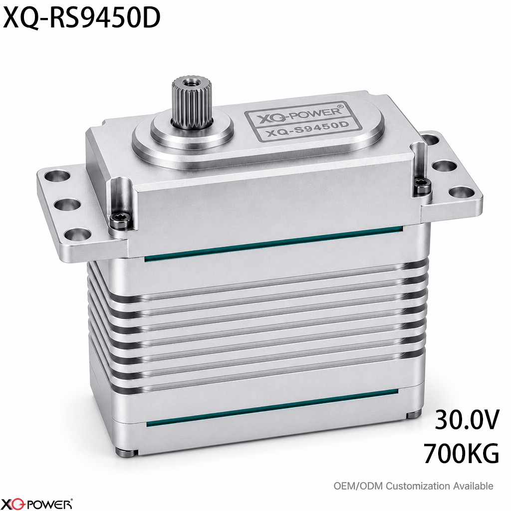
The XQ-RS9450D is a 700kg-class RS485 industrial brushless actuator intended for high-load, long-distance motion control. The product page specifies 700kg torque, 0.21 sec/60° at 30V, a 24–30V operating range, RS485 differential communication, a magnetic encoder, a CNC-machined aluminum case, toughened steel gears, eight industrial ball bearings, and a 25T, φ11.98mm output shaft.
Rather than repeating a standard product-page summary, this guide focuses on a practical engineering question: How should an integrator evaluate a 700kg RS485 actuator when the machine has long cable runs, multiple motion nodes, and high mechanical inertia?
Treat RS485 as part of the motion architecture
RS485 is not simply a connector choice. In a distributed motion system, the physical bus, controller software, node identity, power distribution, and feedback strategy must work as one design.
Before selecting the RS9450D for a production axis, document:
- the number of actuators on the network;
- the approximate cable path and branch layout;
- the required update rate and response behavior;
- how each actuator will be addressed and commissioned;
- which feedback values the controller needs during operation;
- how the communication bus will be tested after installation.
The RS9450D is relevant when the machine benefits from a shared differential communication architecture instead of independent signal wiring for every actuator. The correct implementation still depends on the controller, communication map, cable design, and system-level testing.
Decide whether 700kg torque solves the real mechanical problem
A high torque rating does not replace a load calculation. For a robotic joint, positioning axis, or heavy linkage, the required output torque can include acceleration torque, gravity torque, friction, external disturbance, and shock loads.
A useful selection review separates four values:
- Static holding torque — the torque required to hold the mechanism in position.
- Acceleration torque — the additional torque required to change the speed of a high-inertia load.
- Continuous operating torque — the torque required during the normal duty cycle.
- Transient or shock torque — short-duration loads caused by contact, sudden stops, or mechanical disturbance.
The RS9450D’s published 700kg torque point is specified at 30V. It should therefore be compared with the actual torque requirement at the output shaft, not with the load mass alone. A heavier payload does not automatically require the same actuator in every mechanism because lever arm length, acceleration, gearing, and counterbalance also change the torque demand.
Use the 30V rating as a complete electrical-system decision
The product page lists a 24–30V voltage range and identifies the 30V point for the 700kg torque and 0.21 sec/60° operating specification. A system designer should evaluate the actuator, supply, controller, wiring, connectors, and emergency-stop strategy together.
For a prototype or production machine, verify:
- whether the controller and drive architecture support the selected operating voltage;
- whether the supply can handle acceleration and load-change current demand;
- whether voltage drop is acceptable at the farthest actuator;
- whether cable and connector selections match the current and installation environment;
- whether the software limits travel and handles communication faults safely;
- whether the mechanical stop strategy prevents excessive output-shaft loading.
The goal is not simply to apply the highest available voltage. The goal is to create a repeatable electrical operating point that the controller and the mechanical system can support.
Build the bus around serviceability and diagnostics
A long-distance RS485 network should be designed for commissioning and troubleshooting, not only for the first successful movement.
A practical integration plan should define:
- a clear node naming and addressing scheme;
- a repeatable procedure for adding or replacing an actuator;
- cable labels that match the controller configuration;
- a method for testing each node before the entire machine is energized;
- a log of actuator position, voltage, temperature, and load-related feedback where available;
- a fault-isolation process that distinguishes a mechanical problem from a bus or power problem.
The RS9450D product page identifies magnetic-encoder feedback and RS485 differential communication. These features are valuable only when the control software exposes the relevant information in a form that the operator or maintenance team can use.
Check the mechanical interface before ordering production units
The actuator is specified with a 25T, φ11.98mm output shaft, a toughened steel gear train, eight industrial ball bearings, and a CNC-machined aluminum case. Those features should be reviewed together with the joint bracket and linkage.
Before approving the mounting design, confirm:
- the horn or adapter matches the 25T output interface;
- the bracket resists torsion under peak load;
- the linkage avoids unnecessary side loading;
- the output axis is aligned with the driven mechanism;
- the actuator mass is included in the moving-link inertia calculation;
- the mounting structure allows access to the connector and fasteners.
At 700kg-class torque, a flexible bracket can become the limiting component even when the actuator itself has sufficient output capability. The mechanical interface should therefore be tested under the same load direction and acceleration profile expected in the final machine.
Compare RS485 with PWM for the actual installation
The product page positions the RS9450D around RS485 differential communication. The FAQ and application questions engineers commonly ask make the comparison with conventional PWM especially relevant.
When RS485 is the stronger fit
RS485 can be attractive when the machine has multiple actuators, longer cable paths, shared diagnostics, or a controller that already uses serial industrial communication. A multi-node approach can reduce duplicated signal wiring and provide a clearer addressing model.
When PWM may be simpler
PWM can remain practical for a small number of actuators controlled by a conventional receiver or servo controller. If the system does not need node addressing, telemetry, or a shared serial bus, a PWM architecture may require less software integration.
The best choice depends on the machine. Use RS485 when the benefits of a shared, addressable motion network outweigh the added commissioning and protocol work.
Run tests that represent the final machine
Bench testing is useful for checking basic movement, but it does not prove that a 700kg-class actuator is suitable for a complete robotic or automation axis.
A representative validation plan should include:
- No-load communication test — Verify node discovery, addressing, commands, feedback, and fault reporting.
- Mounting validation — Install the actuator on the final or representative bracket and inspect structural movement.
- Static load test — Check holding behavior at defined positions and load points.
- Dynamic load test — Reproduce the expected acceleration, deceleration, travel, and duty cycle.
- Long-cable test — Test the actual cable length, routing, connectors, and node arrangement.
- Fault-recovery test — Confirm the system response to a disconnected node, power interruption, or communication fault.
Record controller settings, bus configuration, supply voltage, load conditions, and measured temperatures so the result can be repeated by another engineer.
Frequently Asked Questions
The product page identifies RS485 differential communication and describes the actuator for high-load, long-distance motion control. Multi-node operation still requires confirmation of the communication protocol, addressing method, wiring topology, termination, and controller compatibility for the target system.
Not in every installation. RS485 is generally more relevant when the system needs shared bus communication, multiple nodes, longer cable paths, or feedback integration. PWM may be simpler for a small, conventional servo system. The correct choice depends on the controller and network requirements.
The RS9450D product information specifies a 25T, φ11.98mm output shaft. Match that interface with a compatible horn or adapter, then verify bracket stiffness, linkage alignment, side loading, and the torque path into the joint.
The product page positions the RS9450D as an industrial actuator for high-load motion control. An RC or aircraft installation would require a separate review of voltage, receiver or flight-controller compatibility, actuator mass, speed, mechanical loading, and mounting structure. Do not infer suitability from torque alone.
It can be considered when the arm requires the specified torque class and can accommodate the actuator’s 24–30V architecture, RS485 interface, output shaft, mechanical envelope, and duty cycle. A prototype should reproduce the arm’s actual payload, acceleration, and cable arrangement.
Provide the torque profile, speed requirement, supply voltage, number of nodes, approximate cable layout, communication controller, output interface, mounting dimensions, duty cycle, and validation criteria. These details allow the actuator to be evaluated against the real axis rather than a generic application label.
Selection summary
The XQ-RS9450D is best evaluated as a 700kg-class RS485 motion node, not as an isolated torque component. Its published 30V operating point, 0.21 sec/60° speed, RS485 differential communication, magnetic encoder, CNC-machined aluminum case, toughened steel gear train, eight industrial ball bearings, and 25T, φ11.98mm output shaft define a system-level design opportunity for heavy robotics and industrial automation.
For an integrator, the next step is an application-specific test: use the intended controller, cable layout, mounting bracket, supply voltage, node arrangement, and dynamic load. That test will reveal whether the RS9450D fits the complete motion architecture.