
XQ-S9750DC: How to Integrate a 1000kg.cm CAN Bus Actuator into Heavy-Duty Motion Systems
A high-torque actuator is only one part of a reliable distributed motion system. When a large UAV, heavy vehicle, or robotic mechanism needs fast coordinated movement, the engineering team must evaluate the actuator output, the CAN network, the flight or vehicle controller, the power architecture, and the mechanical load path as one system.
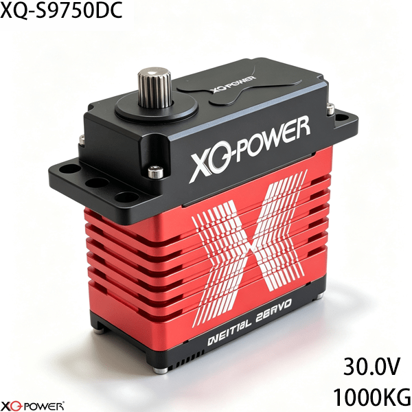
The XQ-S9750DC is a 1000kg.cm-class industrial brushless actuator built for CAN Bus integration. The product page specifies 1000kg.cm torque, 0.25 sec/60° speed at 30V, a 30V drive platform, CAN Bus communication, and support for standard UAVCAN-oriented control applications. It also identifies a full CNC-machined aluminum case and toughened stainless-steel gears.
This guide takes a system-integration approach rather than repeating a product-page summary. It explains how to decide whether a CAN Bus actuator belongs in a heavy-lift UAV, vehicle subsystem, large robotic joint, or other distributed motion application, and how to prepare a meaningful prototype test before production approval.
Start with the CAN network architecture
Before mounting the first actuator, define the complete network. A useful system diagram should show:
- the flight controller, vehicle controller, or industrial motion computer;
- the CAN transceiver and bus connection;
- every actuator node and its CAN identity;
- message groups for commands, feedback, diagnostics, and status;
- bus termination locations and cable routing;
- power entry points and the farthest actuator;
- the mechanical axis controlled by each node;
- the intended state after a communication timeout or node fault.
The actuator, controller, wiring, and software should be treated as one distributed system. A network may be mechanically strong but difficult to commission if the node map, message priorities, and recovery behavior were never documented.
Decide whether CAN Bus fits the application
CAN Bus is a strong candidate when several motion nodes must share a coordinated control architecture and the system needs structured communication between the controller and each actuator.
Evaluate CAN Bus when:
- the flight or vehicle controller already provides a CAN interface;
- several actuators need coordinated updates;
- the system benefits from node identity and message-based feedback;
- cable routing is distributed across a large mechanism;
- the engineering team already has CAN diagnostics and termination practices;
- the application needs a defined response to communication errors.
A different interface may be simpler for a small local installation with only one or two actuators and no shared network. The correct choice should follow the controller, node count, timing requirements, feedback model, cable plan, and maintenance workflow.
Build a node and message map before writing firmware
A CAN network becomes easier to maintain when every node and message has a documented purpose. Before software integration, record:
- actuator asset label and physical axis name;
- CAN node identity;
- command message and data fields;
- target position format and unit;
- feedback message and data fields;
- status and diagnostic messages;
- heartbeat or timeout behavior, where supported;
- startup, enable, stop, and reset behavior;
- firmware or configuration version;
- acceptance-test result.
Use one naming convention across the wiring diagram, flight-controller configuration, vehicle software, HMI, test report, and maintenance record. The technician servicing the machine should be able to connect a physical actuator to its digital identity without reverse-engineering the network.
Separate motion messages from diagnostic messages
CAN Bus bandwidth is a system resource. The controller should allocate message timing between position commands, feedback, status, fault handling, and maintenance records.
For each axis, define:
- command update interval;
- feedback update interval;
- diagnostic message interval;
- message priority;
- maximum acceptable response delay;
- behavior after a missed message;
- behavior when several axes move at once;
- logging requirements for flight, vehicle, or factory testing.
Do not assume that sending every available data field at the highest possible rate will improve control. Fast motion data and slower maintenance data can have different priorities. Confirm the current CAN message definitions, supported UAVCAN functions, update behavior, and recovery rules in the applicable technical documentation before finalizing firmware.
Calculate torque at the joint instead of using payload alone
The S9750DC product page identifies 1000kg.cm torque and 0.25 sec/60° at 30V. These values describe actuator performance under the published condition; they are not a direct payload rating for every mechanism.
Build a worst-case torque model that includes:
- payload mass and center of gravity;
- distance from the output shaft to the load;
- gravity torque at the least favorable angle;
- acceleration and deceleration torque;
- transmission ratio and mechanical efficiency;
- aerodynamic, vehicle, or external forces where applicable;
- impact and transient loads;
- holding time and repeated-cycle duty;
- required design margin.
For a heavy-lift UAV control surface or large robotic joint, include the inertia of the driven mechanism in the calculation. For a vehicle actuator, include the forces that occur during steering, lifting, suspension, or other representative movement rather than validating only a static bench load.
Match the 30V drive platform to the power system
The product page identifies 30V as the operating point for the published torque and speed figures. The power system should be evaluated during acceleration, load reversal, simultaneous node movement, and the longest expected holding period.
Verify:
- supply capacity during peak movement;
- voltage at the actuator terminals;
- cable voltage drop across the full route;
- connector, conductor, and protection ratings;
- current demand when multiple axes move together;
- controller and actuator restart behavior;
- power behavior during a communication fault;
- separation and routing of power and CAN wiring.
Measure at the actuator location, not only at the power source. A supply that appears stable in the controller cabinet may behave differently at a remote node during a high-inertia acceleration event.
Use CAN feedback to improve system observability
A distributed actuator is easier to validate when the controller can observe the behavior of each node. The control software should define what feedback is needed for the application and what action follows an abnormal value.
A commissioning or flight-test record may compare:
- commanded position and reported position;
- command timing and measured response;
- voltage during simultaneous movement;
- temperature across repeated cycles;
- communication errors and recovery events;
- behavior before and after a mechanical adjustment;
- node status during controller restart.
Feedback should first make the system observable. Only after the data fields, update behavior, error state, and controller response have been validated should a value be assigned to a protection or interlock function.
Evaluate CAN Bus for heavy-lift UAV control surfaces
The S9750DC product page identifies heavy-lift UAVs and standard UAVCAN-oriented applications as target use cases. A UAV integration review should cover more than actuator torque.
Confirm:
- flight-controller compatibility with the required CAN or UAVCAN implementation;
- node discovery and identity management;
- command update rate and response timing;
- behavior after a node becomes unavailable;
- power budget for simultaneous control-surface movement;
- mechanical travel limits and neutral-position behavior;
- pre-flight test and fault-logging procedures;
- manual or controlled recovery mode for a communication fault.
The actuator should be tested with the actual controller, wiring length, power system, linkage, and control-surface load. A bench test with a short cable and no representative load cannot replace an integrated flight-system validation.
Review the CNC case and stainless-steel gearing with the structure
The product page identifies a full CNC-machined aluminum case and toughened stainless-steel gears. These features are part of the actuator design, but the surrounding structure still determines how the motion reaches the load.
Check:
- mounting-hole pattern and fastener access;
- output shaft and adapter compatibility;
- alignment between the actuator and driven mechanism;
- bracket stiffness under peak torque;
- radial and axial load strategy;
- independent support bearings for significant side loads;
- mechanical stops and travel limits;
- service access to the connector and fasteners.
Do not use the actuator as the only structural bearing in a custom joint when the linkage creates a large overhung force. An independent support arrangement may improve alignment and reduce unwanted loading on the output assembly.
Commission the CAN actuator in five stages
Stage 1: Verify one CAN node
Connect one S9750DC to the intended controller. Confirm node identity, communication, command direction, travel, feedback, and timeout behavior.
Stage 2: Create the digital asset record
Link the node identity to the actuator label, physical axis, controller configuration, cable route, firmware version, and test fixture.
Stage 3: Add nodes individually
Connect additional actuators one at a time. Confirm that each node has a unique identity and that command and feedback messages are associated with the correct axis.
Stage 4: Run coordinated unloaded motion
Use a low-speed, unloaded profile. Check command timing, message priority, position behavior, voltage stability, temperature trend, and communication recovery.
Stage 5: Apply the representative duty cycle
Use the intended linkage, payload, acceleration, holding time, and repeated-cycle pattern. Record node behavior at the farthest point in the network and under the real power conditions.
Compare CAN Bus, RS485/Modbus, and PWM
| Engineering requirement | CAN Bus | RS485/Modbus | PWM |
|---|---|---|---|
| Distributed motion control | Strong candidate for message-based networks | Strong candidate for register-based networks | Usually requires separate channels |
| Node identity | Defined within the CAN architecture | Defined through device addresses | Not inherent to a shared network |
| UAV or vehicle controller integration | Useful when the controller is CAN-based | May require an interface or gateway | Useful for conventional servo outputs |
| Feedback handling | Message-based status and telemetry | Register polling and response handling | Depends on controller and actuator features |
| Commissioning method | Node, message, priority, and termination checklist | Address, register, and timeout checklist | Channel-by-channel setup |
This table is a planning aid. Confirm the controller interface, message definitions, timing, and diagnostic behavior in the current product documentation before selecting the final network architecture.
Frequently Asked Questions
The main reason is the combination of 1000kg.cm-class actuator output and CAN Bus communication. This makes the model relevant to distributed motion systems that need coordinated nodes, structured messages, and controller-level diagnostics.
The product page identifies heavy-lift UAVs and UAVCAN-oriented control applications as target use cases. Confirm flight-controller compatibility, message definitions, power capacity, mechanical travel, control-surface load, and communication-recovery behavior with a representative integrated test.
CAN Bus can be a better fit when several axes share a controller, the system requires node identity, or the software needs structured feedback and diagnostics. PWM may be simpler for a small local mechanism with separate signal channels and limited feedback requirements.
That depends on the complete load path. Calculate torque from payload, lever arm, gravity, acceleration, external forces, shock, transmission efficiency, and duty cycle. Then compare the result with confirmed actuator performance at the selected voltage and operating condition.
Start with one node, record its identity and physical axis, and verify command and feedback messages. Add nodes individually, check for duplicate identities, confirm message association, and run coordinated movement only after each node has a documented configuration.
Monitor the fields confirmed by the current documentation, such as node status, commanded and reported position, communication events, voltage, temperature, and fault state where available. Define units, update behavior, acceptable limits, and recovery actions before testing.
Include the number of axes, torque and speed profile, 30V power architecture, CAN or UAVCAN controller type, required feedback, cable arrangement, message requirements, mechanical interface, payload, duty cycle, sample quantity, and acceptance test.
Final S9750DC selection checklist
Before approving the XQ-S9750DC for a production design, confirm:
- calculated joint or control-surface torque and design margin;
- 30V power capacity and terminal voltage;
- controller compatibility with CAN Bus or UAVCAN-oriented functions;
- node identity and message map;
- command, feedback, timeout, and recovery behavior;
- message timing and priority during simultaneous movement;
- bracket, adapter, linkage, and support-bearing strategy;
- representative-load and repeated-cycle test criteria;
- current mechanical and electrical values from the S9750DC documentation.
The XQ-S9750DC should be evaluated as a distributed CAN motion component rather than as an isolated torque number. Its 1000kg.cm-class output, 30V brushless platform, CAN Bus interface, CNC-machined aluminum case, and toughened stainless-steel gearing make it a candidate for heavy-lift UAV, vehicle, and robotic motion systems. The strongest selection decision will come from a load calculation, a documented message plan, a measured power test, and staged commissioning with the actual controller.