
XQ-RS9750D: How to Design a Long-Distance RS485 Motion Network Around a 1000kg.cm Actuator
A high-torque actuator becomes much more useful in an industrial machine when its communication architecture is planned as carefully as its mechanical output. For a large robot, remote positioning axis, or heavy automation mechanism, the engineering challenge may not be only torque. It may also be how to send commands over a long cable run, identify each node, retrieve feedback, and keep commissioning repeatable in an electrically busy environment.
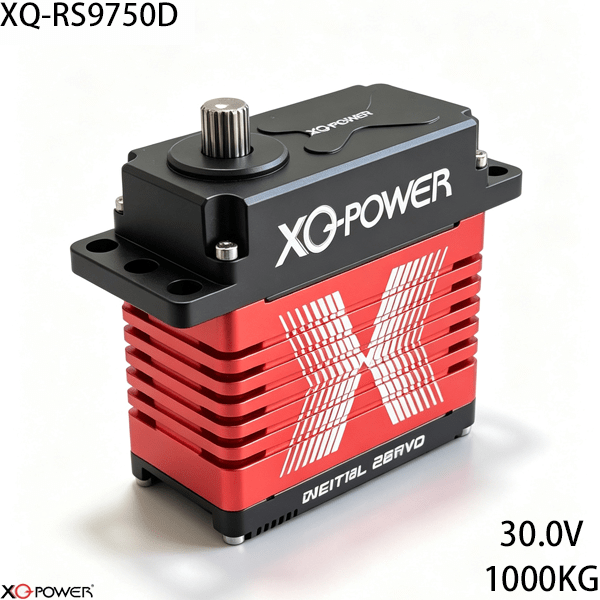
The XQ-RS9750D is a 1000kg.cm-class industrial brushless actuator with RS485/Modbus communication. The product page specifies 980–1000kg.cm / 13,610–13,888oz-in torque at 30V, 0.25 sec/60° at 30V, a 24–30V voltage range, toughened steel gears, a CNC-machined aluminum case, ten ball bearings, and real-time feedback for position, voltage, and temperature. Its defining selection question is therefore not simply “How much torque does it have?” but “Can its RS485/Modbus control model simplify this machine’s distributed motion architecture?”
This article is written as an application and integration guide rather than a second product-page description. It focuses on network planning, Modbus commissioning, power distribution, high-inertia mechanics, and the questions an OEM should resolve before requesting a sample.
Start by mapping the RS485 network
Before mounting the first actuator, draw the complete communication and power layout. The diagram should identify:
- the PLC, motion controller, or industrial computer;
- the RS485 master interface and transceiver;
- every actuator node and its Modbus address;
- cable route, branch points, termination points, and service connectors;
- power-injection locations and the expected voltage at the farthest node;
- the mechanical axis controlled by each actuator;
- required feedback registers and polling frequency;
- the intended state of the machine after a communication interruption.
RS485 is a differential bus architecture, so the physical network should be treated as part of the control system. Avoid designing the wiring as an afterthought. The control engineer and mechanical engineer should agree on node order, cable routing, grounding approach, and access for replacing one actuator without losing track of the address map.
Decide whether RS485/Modbus fits the controller
The RS9750D product page identifies PWM, CAN Bus, and RS485 (Modbus) in its communication matrix, while the product itself is positioned as an RS485 industrial actuator. Compare the interfaces by the way the machine is built.
RS485/Modbus is a strong candidate when:
- a PLC or industrial controller already communicates through Modbus registers;
- actuators are distributed over a machine rather than mounted beside the controller;
- the software team needs explicit node addressing;
- position, voltage, and temperature feedback must be read by supervisory software;
- the commissioning team wants a documented register map for every axis.
PWM may be simpler when:
- the system has only a few local actuators;
- the controller already provides conventional servo channels;
- there is no need for register polling or shared-bus diagnostics;
- separate signal paths do not create a wiring burden.
CAN Bus may be preferable when:
- the existing control platform is already CAN-based;
- the machine has a distributed CAN motion architecture;
- the engineering team has already standardized its CAN diagnostics and termination practices.
The correct choice depends on the controller, network length, node count, feedback requirements, and service process. RS485 is not automatically the right answer for every axis, but it is especially relevant when Modbus compatibility and distributed wiring are central to the project.
Build a useful Modbus register plan
A bus is valuable when each register has a clear engineering purpose. Before software integration, document the following for every RS9750D node:
- Modbus address and physical axis name;
- command register and expected data type;
- position unit, resolution, and permitted range;
- feedback registers for position, voltage, and temperature;
- response timeout and retry behavior;
- startup, enable, stop, and fault-reset commands;
- behavior after communication loss;
- firmware or configuration version.
Do not let the address map exist only inside one engineer’s laptop. Store it with the machine configuration and attach an asset label to every actuator. This turns a multi-node installation into a serviceable system instead of a collection of individually configured devices.
Plan polling and motion timing together
Reading more data is not always the same as improving control. The controller should allocate bus time between command updates, feedback polling, fault checks, and diagnostics.
For each axis, define:
- command update interval;
- feedback polling interval;
- priority of motion data over maintenance data;
- maximum acceptable response delay;
- action after a missed response;
- behavior when multiple axes move simultaneously.
A machine that polls every diagnostic field at the same priority as a motion command may create unnecessary traffic. Separate fast control information from slower maintenance records where the controller and protocol implementation allow it. Confirm the actual RS485/Modbus timing, register map, and supported addressing method in the current technical documentation before finalizing the software design.
Evaluate 1000kg.cm torque at the joint, not only at the output
The product page identifies approximately 980–1000kg.cm torque at 30V. Whether that is sufficient depends on the mechanism’s lever arm, payload, acceleration, gravity, friction, and shock loading.
Create a worst-case torque model containing:
- payload mass and center of gravity;
- distance from the output shaft to the load;
- gravitational torque at the least favorable angle;
- acceleration and deceleration torque;
- transmission ratio and efficiency;
- external forces and impact events;
- holding time and repeated-cycle duty;
- required engineering margin.
A 1000kg.cm-class actuator can still be a poor fit if the bracket flexes, the linkage creates excessive side load, or the upstream robot joint must carry the actuator mass. Review the complete force path from the output shaft through the adapter and bracket into the machine frame.
Include the 30V power system in the communication design
The RS9750D page specifies 30V for its highest published torque and speed figures, with a 24–30V operating range. Power distribution and RS485 communication should be designed together because cable routes, grounding, voltage drop, and electrical noise can affect both motion performance and data reliability.
Check:
- supply capacity during acceleration and load reversal;
- terminal voltage at the farthest actuator;
- current demand when multiple axes move together;
- fuse, connector, and conductor ratings;
- controller and actuator restart behavior;
- cable separation between power and communication paths;
- the machine response to a low-voltage or disconnected node.
Use the official electrical specification and a representative motion profile to size the supply. Do not use idle current as the only design input for a high-inertia axis.
Use feedback to improve commissioning and maintenance
The product page describes real-time feedback for position, voltage, and temperature. These values can support a more disciplined commissioning process when they are tied to defined acceptance criteria.
For example, the commissioning record can compare:
- commanded position against reported position;
- actuator voltage during simultaneous movement;
- temperature across repeated cycles;
- load-related behavior before and after a mechanical adjustment;
- node response time and communication errors;
- behavior after a controller restart.
Feedback should first be used to make the machine observable. Only after the data format, update behavior, failure state, and controller logic are validated should it be assigned to a protective or interlock function.
Check the mechanical envelope and support strategy
For an RS9750D purchase, confirm the current mechanical drawing before finalizing the bracket. The mechanical envelope, mounting pattern, output interface, and actuator mass should be taken from the current RS9750D documentation rather than inferred from a similar-looking actuator.
The mechanical review should cover:
- mounting-hole pattern and fastener access;
- output shaft and adapter compatibility;
- clearance around the actuator body;
- actuator mass in the moving-link calculation;
- cable and socket access during service;
- radial and axial load strategy;
- independent support bearings where the linkage creates side loads;
- mechanical stops and travel limits.
The actuator should not be expected to serve as the only structural bearing for every custom joint. An independent support arrangement may be appropriate when the driven mechanism produces significant overhung or side loading.
Commission the RS485 actuator network in five stages
Stage 1: Configure one node
Connect one RS9750D, assign its address, verify Modbus communication, check direction and travel, and record the returned feedback values.
Stage 2: Create the asset record
Link the node address to the actuator label, physical axis, controller configuration, cable route, and firmware or parameter version.
Stage 3: Add nodes individually
Add each actuator one at a time. Confirm that the new node responds at the expected address and that no duplicate address or unexpected response is present.
Stage 4: Run coordinated motion
Start with an unloaded, low-speed profile. Confirm command timing, feedback polling, position behavior, voltage stability, temperature trend, and communication error handling.
Stage 5: Apply the representative duty cycle
Use the intended payload, acceleration, hold time, and repeated-cycle pattern. Record power and communication behavior at the most distant actuator, not only at the controller cabinet.
Compare RS485/Modbus with CAN Bus and PWM
| Engineering requirement | RS485/Modbus | CAN Bus | PWM |
|---|---|---|---|
| PLC register integration | Strong candidate | Depends on controller gateway | Usually requires separate channels |
| Node addressing | Supported through the bus design | Supported through CAN architecture | Not inherent to a shared signal bus |
| Long distributed wiring | Evaluate cable, termination, and noise plan | Evaluate CAN topology and termination | Separate signal wiring may grow quickly |
| Telemetry polling | Fits register-based feedback workflows | Fits message-based feedback workflows | Depends on actuator and controller features |
| Commissioning method | Address map and register checklist | Node and message configuration | Channel-by-channel setup |
This table is a planning aid, not a substitute for the actuator manual or controller documentation. The best protocol is the one the engineering team can configure, test, diagnose, and maintain consistently.
Frequently Asked Questions
Its application focus is the combination of 1000kg.cm-class motion capability and RS485/Modbus industrial communication. That combination allows engineers to plan addressed nodes, register-based commands, feedback polling, and distributed machine diagnostics instead of relying only on separate PWM channels.
It is designed to be evaluated for industrial RS485 motion networks where the controller, cable route, node addressing, termination, power distribution, and feedback strategy are properly engineered. The final distance and network limits must be confirmed using the controller and actuator documentation for the intended installation.
The product page identifies real-time telemetry for position, voltage, and temperature. Confirm the exact Modbus registers, units, update behavior, and response timing before implementing monitoring, logging, or supervisory control.
That depends on the joint geometry and duty cycle. Calculate the required output torque from payload, lever arm, gravity, acceleration, friction, shock, and transmission efficiency. Then compare the result with the confirmed actuator performance at the selected voltage and operating condition.
Begin with one actuator, assign and record its address, then add nodes individually. Maintain a physical label and a software register for every axis. Before coordinated motion, scan for duplicate or unexpected responses and store the final address map with the machine configuration.
Cable routing should follow the system’s electrical-noise and grounding design. Keep the communication path, termination, shielding, connector selection, and power distribution consistent with the actuator and controller documentation. Validate the farthest node while the real motion profile is running.
Include the number of axes, required torque and speed, 24–30V power architecture, controller type, RS485/Modbus requirements, feedback fields, cable length, node arrangement, mechanical envelope, output interface, duty cycle, payload, quantity, and acceptance test.
Final RS9750D selection checklist
Before approving the XQ-RS9750D for a production machine, confirm:
- calculated joint torque and required margin;
- 30V performance requirement and selected operating voltage;
- controller compatibility with RS485/Modbus;
- node address plan and register map;
- communication timing, timeout, and recovery behavior;
- power capacity and voltage at the farthest actuator;
- mounting, output adapter, side-load, and support-bearing strategy;
- required position, voltage, and temperature feedback;
- representative-load and repeated-cycle test criteria;
- final mechanical and electrical values from the current RS9750D documentation.
The XQ-RS9750D should be evaluated as a networked motion component, not as an isolated torque figure. Its 1000kg.cm-class output, 30V brushless platform, RS485/Modbus communication, feedback capability, CNC-machined aluminum case, toughened steel gears, and ten-bearing support system make it a candidate for high-inertia industrial axes. The strongest selection decision will come from a complete load model, a documented register plan, measured power performance, and a staged multi-node commissioning test.