
XQ-S9750D: How to Specify a 1000kg.cm Actuator for High-Inertia Industrial Motion
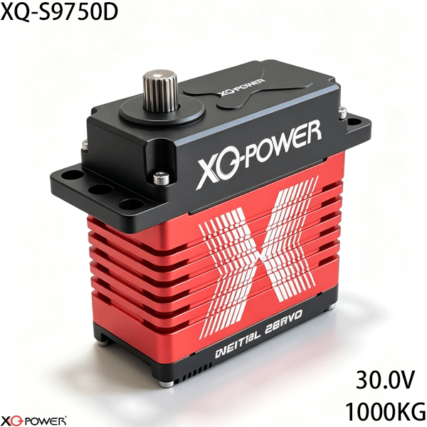
When a robotic joint or industrial mechanism moves a high-inertia load, selecting an actuator is not simply a matter of choosing the largest torque number. The engineering team must also validate acceleration, mechanical leverage, power delivery, thermal behavior, feedback, communications, and the duty cycle of the complete machine.
The XQ-S9750D is a 1000kg.cm-class brushless industrial servo intended for heavy-duty motion control. The product page specifies a 30V operating point, approximately 980–1000kg.cm / 13,610–13,888oz-in torque at 30V, 0.25 sec/60° at 30V, PWM/CAN Bus/RS485 (Modbus) communication, a CNC-machined aluminum case, toughened steel gears, and ten industrial ball bearings. The supplied product reference image also identifies the S9750D and shows a 120.0 × 60.0 × 111.5mm envelope, approximately 1,750g ±0.2, a 30V brushless servo, and a stated peak-current figure of 26A.
This guide takes a system-engineering approach rather than repeating a catalogue description. It explains how to determine whether a 1000kg.cm actuator belongs in a robot joint, heavy linkage, positioning mechanism, winch-style motion system, or other high-load application.
Start with the load path, not the servo catalogue
The first question is not “Can the servo produce 1000kg.cm?” It is “How much torque reaches the output shaft during the worst motion condition?”
Build a load-path model that includes:
- payload mass and center of gravity;
- linkage length and transmission ratio;
- gravitational torque at the most demanding angle;
- acceleration and deceleration torque;
- friction and mechanical resistance;
- shock or transient loads;
- counterbalance behavior;
- required safety margin and duty cycle.
A high-torque servo may be appropriate for a large robotic joint, but the surrounding bracket, horn, shaft adapter, and linkage must transfer the load without excessive flex. If the mechanical structure bends, a larger actuator does not automatically produce more accurate motion.
Use torque and speed together
The S9750D product page identifies approximately 980–1000kg.cm torque at 30V and a 0.25 sec/60° operating speed at 30V. Those two figures should be evaluated together with the actual motion profile.
For each axis, document:
- the required angular travel;
- the desired move time;
- the payload at the farthest position;
- the expected acceleration;
- the number of cycles per hour;
- the time spent holding position;
- the permitted temperature rise and maintenance interval.
A mechanism that needs high peak torque but moves occasionally is a different application from a mechanism that repeats fast movements continuously. The final selection should be based on a measured or calculated motion profile, not only on the maximum static load.
Check the mechanical envelope before prototype assembly
The reference image identifies an actuator envelope of 120.0 × 60.0 × 111.5mm and a mass of approximately 1,750g ±0.2. These values matter because actuator size and mass become part of the joint design.
Before ordering a prototype, check:
- clearance around the 120.0 × 60.0 × 111.5mm body;
- mounting-hole position and fastener access;
- output shaft alignment with the driven joint;
- adapter, horn, or coupling compatibility;
- effect of 1.75kg actuator mass on the moving link;
- cable exit direction and service access;
- stiffness of the mounting plate under the expected load.
A heavy actuator mounted near the end of a robotic arm can increase the moment seen by the upstream joint. Perform the complete arm calculation with the actuator mass included.
Choose the communication interface around the controller
The S9750D supports PWM, CAN Bus, and RS485 (Modbus) according to the product page. The best interface is the one that matches the controller, network architecture, feedback requirements, and maintenance workflow.
Choose PWM when simplicity is the priority
PWM may suit a smaller installation or a controller that already provides conventional servo channels. It can be a practical option when the system does not need multi-node addressing, register-based feedback, or a shared industrial bus.
Choose CAN Bus for distributed motion networks
CAN Bus is worth evaluating when multiple motion nodes share a distributed control architecture. The design team should confirm node addressing, message scheduling, bus termination, fault handling, and controller compatibility before scaling the network.
Choose RS485 with Modbus for PLC-oriented systems
RS485 with Modbus can fit a PLC, HMI, or SCADA architecture that already uses register-based industrial communication. Confirm the register map, baud rate, address assignment, polling behavior, and timeout handling in the applicable technical documentation.
Protocol selection is therefore a system decision, not a ranking of interfaces. The same S9750D actuator can require very different integration work depending on whether it is controlled by a PWM channel, a CAN network, or a Modbus master.
Plan the 30V power system around peak demand
The product page and supplied reference image both identify 30V as the principal high-output operating point. The image states a 26A peak-current figure. A power design should treat this as a planning signal and verify the final current requirement against the official electrical specification and the real motion profile.
Measure or calculate:
- supply capacity during acceleration;
- voltage drop at the actuator terminals;
- current when several axes move simultaneously;
- fuse, connector, and cable ratings;
- regenerative or deceleration behavior;
- controller restart behavior after a supply interruption;
- available margin for future payload changes.
Do not size the supply from idle current alone. A 1000kg.cm-class actuator can impose a very different demand during acceleration, stall prevention, or a rapid change in load direction.
Treat feedback as part of the control strategy
The product page describes real-time telemetry for position, voltage, and temperature. Feedback becomes valuable when the control software turns it into a defined action.
Examples include:
- comparing commanded and measured position;
- detecting an abnormal work-load trend;
- identifying a power-supply drop at the actuator;
- recording temperature during repeated cycles;
- stopping or limiting a motion sequence after a configured fault;
- creating maintenance records for high-cycle joints.
Before using telemetry in a protection or interlock function, confirm the data fields, units, update rate, communication behavior, and failure state. A feedback value should not be treated as a safety function until the complete control system has been validated for that purpose.
Match the gear train and bearing system to the joint design
The product page identifies toughened steel gears and ten industrial ball bearings. Those features are relevant to the load path, but they do not eliminate the need to control side loads, misalignment, and shock.
The mechanical review should include:
- radial and axial forces at the output interface;
- unsupported overhung loads;
- bearing loads created by the linkage;
- gear backlash requirements for the application;
- alignment between the servo and the driven shaft;
- mechanical stops and travel limits;
- lubrication and service instructions from the manufacturer.
For a high-inertia robot, use a rigid adapter and keep the driven load centered wherever the design allows. A joint that places a large side load on the output assembly may require an independent support bearing rather than asking the actuator to carry every structural force.
Validate the actuator with a staged test plan
A staged test catches integration problems before the full mechanism is exposed to maximum load.
Step 1: Bench communication test
Connect one actuator and verify the chosen PWM, CAN Bus, or RS485/Modbus interface. Confirm command direction, travel limits, feedback values, and controller fault handling.
Step 2: Unloaded mechanical test
Install the actuator in the intended bracket and coupling. Run the full travel range at low speed and check for interference, unexpected noise, flex, and connector movement.
Step 3: Representative-load test
Add a representative payload and linkage. Record current, terminal voltage, position error, temperature, cycle time, and any communication events.
Step 4: Repeated-cycle test
Run the intended duty cycle rather than a single demonstration movement. Include the longest hold periods and the most demanding acceleration and deceleration phases.
Step 5: Fault and recovery test
Test communication loss, controller restart, power interruption, and a disconnected feedback condition. Define the desired state of the mechanism before the actuator enters production service.
Compare the S9750D with a smaller actuator by system cost
A smaller actuator may appear cheaper, but the system cost can increase if the mechanism needs additional gearing, counterbalance hardware, separate feedback, or a more complex bracket. Conversely, using a 1000kg.cm-class actuator where the load is modest can add unnecessary mass and power demand.
Use this decision table during concept review:
| Engineering question | If the answer is yes | Selection implication |
|---|---|---|
| Does the axis require very high output torque? | The joint has a high load or long lever arm | Evaluate the S9750D torque class and complete load path |
| Does the axis need distributed feedback? | Position, voltage, or temperature must be monitored | Compare CAN Bus and RS485/Modbus integration requirements |
| Is the controller already PWM-based? | The project has few nodes and simple commands | Evaluate PWM first, then compare the cost of adding telemetry |
| Is actuator mass critical? | The servo is mounted on a moving link | Include the approximately 1,750g mass in the whole-arm calculation |
| Is the motion repetitive? | The machine runs many cycles | Validate current, temperature, and duty cycle with a representative test |
Frequently Asked Questions
The S9750D should be evaluated for high-inertia motion systems that require the published torque class, 30V operating point, and a compatible PWM, CAN Bus, or RS485/Modbus control architecture. Candidate applications include large robotic joints, heavy automation mechanisms, positioning axes, and other engineered motion systems where the full load path can be validated.
That depends on payload, lever arm, acceleration, gravity, friction, shock, and duty cycle. Calculate the worst-case output torque at the joint and compare it with the actuator’s confirmed performance at the selected voltage. Do not size the joint from payload mass alone.
Use PWM when the system is small and conventional servo control is sufficient. Consider CAN Bus for distributed motion networks and RS485/Modbus for PLC-oriented register communication. The final choice should follow the controller, node count, feedback requirements, wiring plan, and maintenance process.
The product page identifies real-time telemetry for position, voltage, and temperature. Confirm the exact fields, units, update behavior, and communication format in the applicable technical documentation before implementing alarms, logging, or closed-loop supervisory functions.
Start with the published electrical requirements and the reference image’s 26A peak-current figure, then verify the value against the official datasheet and your real motion profile. Include simultaneous axis movement, cable voltage drop, connector ratings, acceleration demand, and restart behavior in the power study.
No. The bracket, adapter, linkage, and driven structure still need to transfer torque without excessive deflection. A flexible mounting plate can reduce positioning accuracy and create loads that the actuator was not intended to carry.
Provide the axis count, torque and speed profile, supply voltage, controller and protocol, required telemetry, mechanical envelope, output interface, duty cycle, payload, quantity, and acceptance test. A complete application brief allows the supplier to evaluate the actuator against the actual machine.
Final selection checklist
Before approving the XQ-S9750D for a production design, confirm:
- the calculated joint torque and required margin;
- the 30V power architecture and peak-current plan;
- the 120.0 × 60.0 × 111.5mm mechanical envelope;
- the approximately 1,750g actuator mass in the system calculation;
- the selected PWM, CAN Bus, or RS485/Modbus interface;
- the required telemetry fields and controller handling;
- the output adapter, bracket stiffness, and side-load strategy;
- the repeated-cycle test and fault-recovery criteria;
- the final low-voltage performance values from the current datasheet.
The XQ-S9750D is best viewed as a complete high-inertia motion subsystem rather than an isolated torque rating. Its 1000kg.cm-class output, 30V brushless platform, multi-protocol control options, CNC-machined aluminum case, toughened steel gears, ten-bearing support system, and compact published envelope make it a candidate for demanding industrial motion designs. The final decision should come from load calculations, power measurements, controller compatibility, and a representative prototype test.