
A multi-axis robot can be difficult to scale when every actuator needs a separate signal path and every diagnostic value is checked independently. A serial-bus architecture changes that design problem: the system engineer must plan node identity, bus access, feedback, power distribution, and commissioning as one coordinated network.
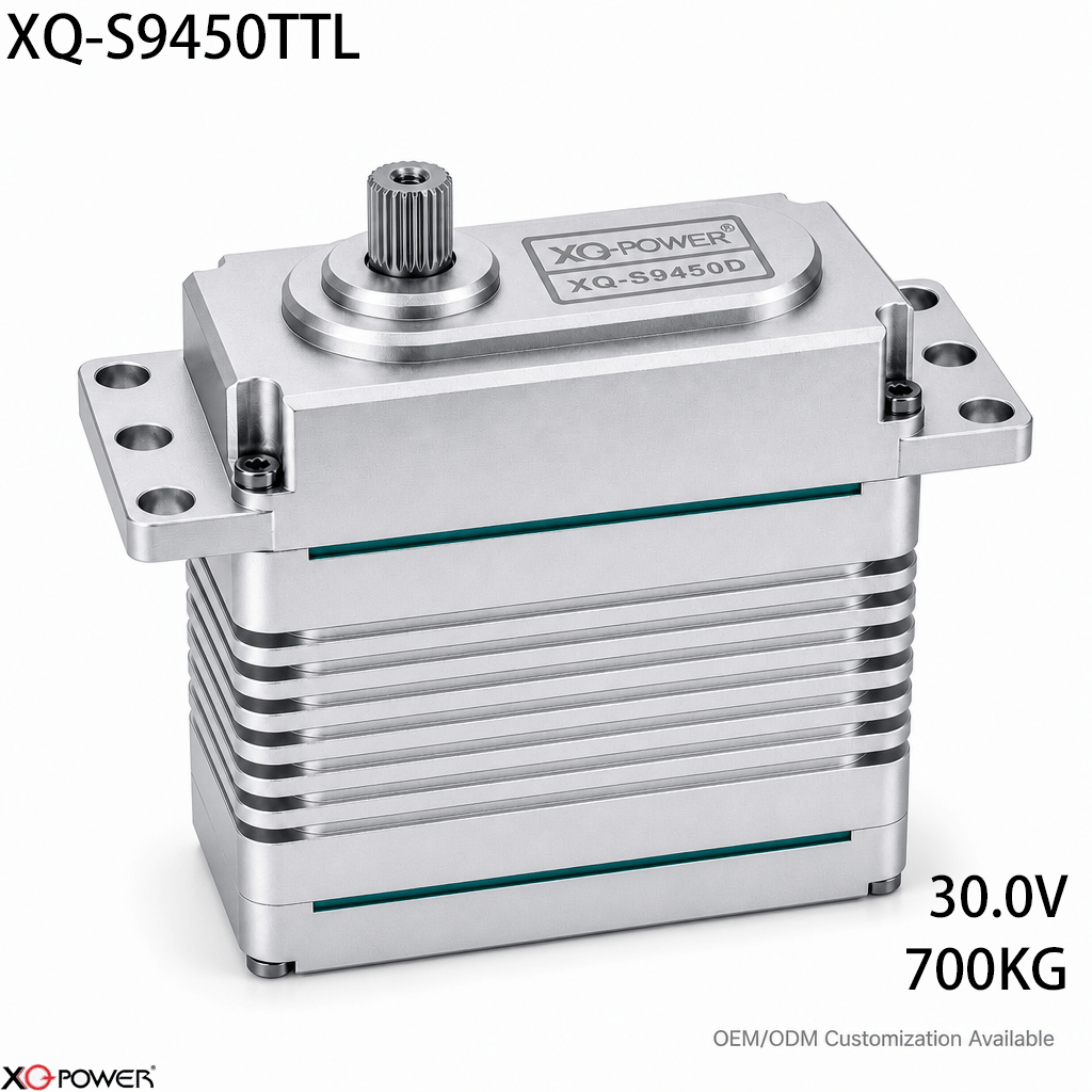
The XQ-S9450TTL is a 700kg-class smart serial-bus brushless actuator for ultra-heavy robotic joints. The product page identifies TTL daisy-chain communication, real-time telemetry, 700kg.cm torque at 30V, 0.21 sec/60° speed at 30V, a 24–30V voltage range, a toughened steel gear train, eight ball bearings, and a CNC-machined aluminum case.
This article is intentionally different from a product-page overview. It focuses on how a robotics developer should decide whether a serial-bus actuator is appropriate for a multi-axis system, how to organize feedback, and how to validate a high-torque network before deploying it on a large mechanism.
Start by drawing the actuator network
Before ordering a group of actuators, draw the complete motion network. A useful first diagram should show:
- the main controller and its serial interface;
- every actuator node and its assigned identity;
- the order of the daisy-chain connections;
- power entry points and cable paths;
- mechanical joints controlled by each node;
- the feedback values required by the supervisory software;
- service access for replacing or commissioning one actuator.
A daisy-chain layout can reduce duplicated signal wiring, but it also makes node planning more important. The control team should know how a single disconnected or misconfigured node affects the rest of the motion sequence before the system is assembled.
Decide when a serial bus is better than PWM
The correct interface depends on the machine’s scale and feedback requirements.
A serial bus is a strong fit when:
- several actuators must be addressed by one controller;
- the system needs real-time position, temperature, voltage, or load feedback;
- the wiring plan benefits from a daisy-chain topology;
- the software team needs node identity and parameter management;
- multiple high-torque joints must be commissioned consistently.
PWM may be simpler when:
- only a small number of actuators are used;
- the controller already provides conventional servo pulses;
- the machine does not need node addressing or feedback registers;
- separate signal channels are acceptable for the installation.
This is not a general claim that one protocol is always better. It is a system decision. The S9450TTL is most relevant when networked control and feedback are valuable enough to justify the additional bus configuration work.
Define what telemetry means in the real machine
“Real-time telemetry” is useful only when the control software knows what to do with the returned data. Before integrating the S9450TTL, define the purpose of each feedback value.
A multi-axis robotics team may use telemetry for:
- confirming that a commanded joint reached its target;
- identifying an unexpected rise in work load;
- recording internal temperature during repeated cycles;
- checking input voltage during simultaneous motion;
- comparing the behavior of multiple joints;
- supporting maintenance and fault investigation.
The product page identifies telemetry for absolute position, internal temperature, input voltage, and work load. Confirm the exact data format, update behavior, units, and controller implementation in the applicable technical documentation before using a value in an alarm or safety-related decision.
Plan node identity before the first power-up
Unique node identity is one of the most important details in a multi-actuator system. A machine should not depend on an operator guessing which actuator is connected to which joint.
Create a commissioning record containing:
- actuator serial number or internal asset label;
- assigned bus ID;
- physical joint or axis name;
- direction and travel settings;
- controller configuration version;
- date and result of the initial motion test;
- any replacement or maintenance history.
For a large robot, label the actuator, cable, controller channel, and mechanical axis with the same naming convention. This makes a failed-node investigation faster and reduces the risk of applying the wrong travel or direction setting to a neighboring joint.
Match the 30V operating point to the power distribution
The S9450TTL product page identifies a 24–30V voltage range and specifies 700kg.cm torque and 0.21 sec/60° at 30V. A multi-axis system must be checked for simultaneous power demand rather than evaluated one actuator at a time.
Verify:
- the supply capacity during synchronized acceleration;
- voltage drop along the power cable path;
- the number of actuators allowed to move at once;
- connector and wiring capacity;
- power-up sequencing and restart behavior;
- the controller response to a low-voltage or disconnected node condition.
A high-voltage actuator network should be validated at the farthest node while the real motion profile is running. The nominal supply value alone does not show what each actuator receives during a rapid load change.
Check the mechanical interface at 700kg.cm
The product information identifies a toughened steel gear train, eight ball bearings, and a precision-machined aluminum case. At this torque class, the actuator should be reviewed together with its mounting plate, horn, linkage, and driven joint.
Before ordering production quantities, confirm:
- the output interface and compatible horn or adapter;
- bracket stiffness under the expected torque direction;
- linkage alignment and side-load behavior;
- the effect of actuator mass on the moving mechanism;
- access to the serial-bus connector and fasteners;
- the load path from the actuator case into the robot structure;
- the mechanical stop and travel-limit strategy.
A serial bus can simplify signals, but it cannot compensate for a flexible bracket or an incorrectly sized linkage. The complete joint must be tested under the same acceleration and load conditions expected in service.
Use the bus for repeatable multi-axis commissioning
A multi-axis machine should be commissioned in stages rather than moving every joint at once.
Stage 1: Identify one actuator
Connect a single actuator, assign its ID, confirm communication, check direction, and record the feedback values returned by the controller.
Stage 2: Add nodes one at a time
Add the next actuator only after the previous node has a documented configuration. Confirm that the new ID, axis name, direction, and feedback values match the commissioning record.
Stage 3: Test coordinated movement
Run a low-speed synchronized motion profile. Check whether the controller receives the expected position, temperature, voltage, and load-related data from every node.
Stage 4: Introduce the representative load
Repeat the motion test with the final or representative linkage, bracket, and payload. Record bus behavior and power-system measurements during acceleration and deceleration.
Stage 5: Test recovery behavior
Disconnect one node, restart the controller, interrupt power, and restore the network. Define the intended state of the remaining joints before the robot enters production.
Compare TTL bus, CAN, and RS485 by application
The S9450TTL is a TTL serial-bus actuator. Other XQ-POWER product variants use CAN or RS485 interfaces. Protocol selection should follow the controller and system architecture.
- TTL serial bus can be attractive for coordinated servo networks with daisy-chain wiring, node IDs, and actuator telemetry.
- CAN Bus may be a better fit when the machine already uses CAN-based distributed control, especially in vehicle or UAV architectures.
- RS485 can be suitable for PLC-oriented serial industrial systems and register-based communication.
- PWM remains practical for simpler installations that do not need network addressing or feedback exchange.
The question for the robotics developer is: Which interface reduces the total integration risk for this controller, node count, wiring plan, and maintenance process?
Frequently Asked Questions
The product page identifies TTL serial-bus daisy-chain communication. A final installation should still confirm the supported node count, addressing method, wiring arrangement, command timing, and controller implementation before building a multi-axis network.
The product information states that real-time telemetry can provide internal temperature for uniquely addressed actuators. Confirm the exact telemetry field, unit, update behavior, and software handling before building a monitoring or alarm function.
The product page FAQ states that motor mode can be selected through the protocol for ultra-high-torque winch applications. Confirm the exact operating mode, command method, speed behavior, duty cycle, and mechanical safety requirements with the applicable technical documentation before using it in a winch.
It can be worthwhile when the machine has several actuators, needs individual node identity, benefits from daisy-chain wiring, or requires telemetry. PWM may be simpler for a small system without network feedback. Compare the full wiring, software, commissioning, and maintenance workload.
It may be considered when the robotic arm requires the specified torque class and can support the 24–30V power architecture, serial-bus wiring, actuator mounting, output mechanics, and duty cycle. Prototype testing should reproduce the arm’s real payload and acceleration.
Provide the number of axes, torque and speed profile, supply voltage, controller type, required telemetry, node arrangement, mechanical interface, duty cycle, quantity, and acceptance criteria. This information lets the engineering team assess the actuator against the actual robot rather than a generic specification.
Selection summary
The XQ-S9450TTL is best evaluated as a 700kg-class serial-bus node for multi-axis robotics. Its published 30V operating point, 0.21 sec/60° speed, 24–30V range, TTL daisy-chain communication, telemetry capability, toughened steel gear train, eight ball bearings, and CNC-machined aluminum case define a networked motion-system project.
For a robotics developer, the practical next step is a staged test: identify one node, add actuators one at a time, verify telemetry, apply the representative load, and test recovery behavior before synchronized operation. That process reveals whether the S9450TTL fits the complete control and mechanical architecture.