
Direct answer: Yes. A dynamic seal around a rotating servo output shaft is a friction interface, so long-term high-frequency motion can gradually change the seal lip, shaft contact surface, and preload condition. Within the specified water depth, speed, load, and duty cycle, a properly designed underwater servo can control the risk. However, prolonged operation beyond the validated envelope—or operation with high pressure, vibration, sediment, or salt-water contamination—can increase wear and eventually allow trace water ingress. A waterproof rating alone should not be treated as proof of unlimited underwater service life.
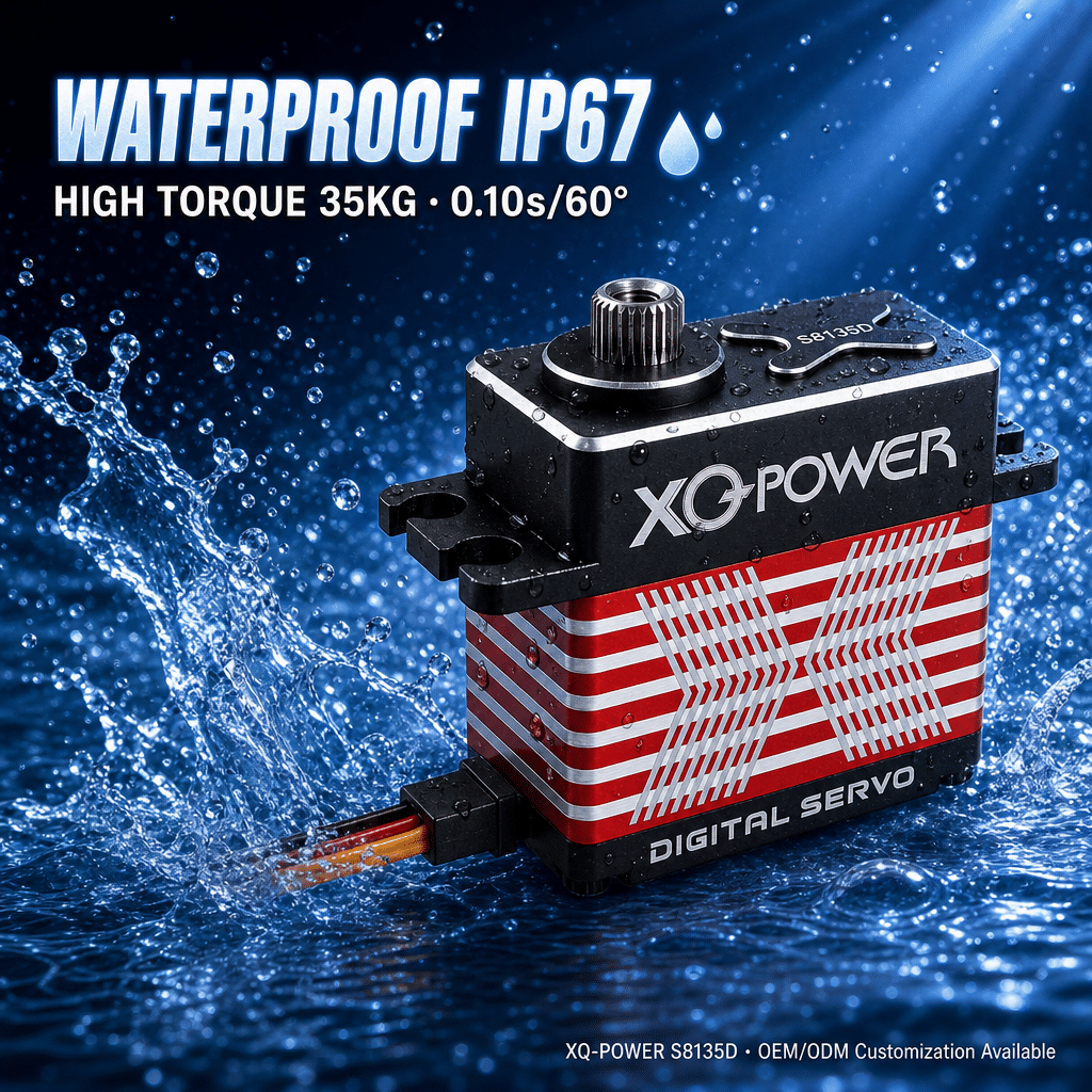
At-a-Glance Engineering Takeaways
- A static housing seal and a rotating output-shaft seal face different wear mechanisms.
- Water depth, shaft speed, oscillation frequency, load, cycle count, and duty cycle must be evaluated together.
- Seal material, lip preload, output-shaft surface condition, bearing support, and alignment influence long-term sealing performance.
- A small leak can begin as a gradual durability issue rather than an immediate functional failure.
- XQ-POWER identifies waterproof brushless servos for subsea ROV applications, but model-level operating limits must be confirmed before deployment.
- The correct verification method is an application-specific underwater durability and immersion test—not a rating label alone.
Why Dynamic Seals Wear During Underwater Servo Motion
An underwater servo typically has two different sealing challenges. The first is the static boundary between the housing, cover, cable exit, and other fixed interfaces. The second is the dynamic boundary where the output shaft rotates or oscillates through a seal.
A static seal can remain compressed without relative movement. A dynamic seal must maintain contact while the shaft changes position repeatedly. That contact creates friction and heat. Over time, the sealing lip and shaft interface can experience polishing, abrasion, loss of elasticity, or changes in contact pressure.
This does not mean that every underwater servo will leak after a certain number of cycles. It means that dynamic sealing is a life-limited engineering interface whose reliability depends on the complete operating envelope. For a high-frequency rotary mechanism, the relevant questions are not only “Is the servo waterproof?” but also:
- At what water depth will it operate?
- What shaft speed and oscillation angle will it experience?
- How many cycles are required over the intended service life?
- What torque and radial or side loads will act on the output shaft?
- Will sediment, salt, or other contamination reach the moving seal?
- How will the assembly be inspected after endurance testing?
How Water Depth Changes the Sealing Load
Water pressure increases the mechanical demand on the sealing system as depth increases. Pressure can change the contact condition between the seal lip and output shaft, increase friction, and place additional load on housing interfaces and cable exits.
The pressure effect is not independent of motion. A servo operating slowly at a shallow depth may experience a different failure mode from a servo oscillating rapidly at a greater depth. The dynamic seal must accommodate both the external pressure and repeated relative movement.
For this reason, a project specification should define a pressure envelope rather than simply state “underwater use.” A useful engineering requirement includes:
- Maximum operating depth or pressure;
- Continuous and peak shaft speed;
- Oscillation angle and reversal frequency;
- Expected torque and side-load conditions;
- Total cycle count and test duration;
- Water type, temperature, sediment, and salt exposure;
- Required post-test insulation and functional checks.
Engineering validation note: The exact allowable depth and duty cycle are model-specific and should be confirmed with XQ-POWER before production deployment.
Which Wear Mechanisms Can Increase Water-Ingress Risk?
Seal-lip wear
The seal lip follows the output shaft surface. Repeated motion can reduce the original contact geometry or alter the lip edge. If contact pressure becomes uneven, a preferential leakage path may develop.
Shaft-surface wear or damage
The output shaft is part of the sealing interface. Scratches, corrosion, roughness changes, burrs, or contamination can damage the lip or prevent uniform contact. Shaft runout and misalignment can create a repeating high-pressure and low-pressure contact pattern.
Loss of preload or elasticity
A seal depends on its material properties and installed compression. Long exposure to temperature, pressure, lubricant, and cycling can change the preload condition. The result may be higher friction, lower sealing contact, or both.
Bearing and alignment effects
The seal cannot compensate indefinitely for excessive shaft movement. Bearing clearance, radial load, angular misalignment, or an unsupported external linkage can move the shaft away from the intended sealing centerline.
Abrasive contamination
Sediment and particles can enter the moving contact zone and act as abrasives. Salt-water contamination can add a chemical and corrosion burden to exposed interfaces. In a high-frequency application, a small amount of contamination can be transported repeatedly across the seal lip.
How to Specify an Underwater Servo for High-Frequency Rotation
Start with the mechanical duty cycle, not with the product label. The selection process should connect the servo output, sealing system, electronics, and mechanism.
Define the motion profile
Record the commanded angle, actual travel, speed, acceleration, reversal frequency, dwell time, and total cycles. A servo that makes a few positioning movements per hour has a different sealing duty from one that oscillates continuously.
Define the torque and external loads
Torque affects motor current, heat generation, gear loading, bearing load, and the mechanical stability of the output shaft. Include the working torque, peak torque, holding torque, and any radial or axial forces introduced by the linkage.
For a high-load underwater mechanism, review XQ-POWER’s high-torque servo category as a starting point, then request model-level confirmation for the required depth, speed, load, and service life.
Define the operating voltage and electrical environment
The selected voltage must be compatible with the vehicle power architecture and controller. Voltage mismatch can affect speed, current, heat, and communication stability. Cable length, connector arrangement, strain relief, and service access should be included in the system design.
Define the sealing and environmental envelope
Specify pressure, temperature, water chemistry, particle exposure, and cleaning or maintenance conditions. “Waterproof” is not a complete duty-cycle specification. The test condition must reproduce the actual pressure and motion combination.
Why Output-Shaft Support and Alignment Matter
A dynamic seal works best when the output shaft is properly supported and aligned. If an external linkage applies side load directly to the servo shaft, the shaft can deflect or orbit under load. That motion increases uneven seal contact and can accelerate wear.
Where the mechanism permits, use an independent bearing or guided support for external loads, while the servo supplies the controlled torque. Check the shaft centerline, mounting-face flatness, linkage geometry, and fastener stiffness before the first immersion test.
The mounting interface should also prevent housing movement. A servo that shifts slightly under reaction torque can transfer repeated misalignment into the output shaft and seal. XQ-POWER’s servo motor technical guide provides a useful starting point for reviewing sizing, mounting, encoder, communication, and environmental-protection questions together.
What Testing Can Reveal Before Production
A robust underwater durability plan should combine functional, pressure, motion, and post-test inspection.
Baseline inspection
Before testing, record the servo’s functional behavior, current, position accuracy, mechanical noise, output-shaft condition, and insulation or electrical checks appropriate to the product design. Photograph the seal and shaft interface if the assembly allows inspection.
Pressure and immersion test
Use the intended water depth or an equivalent pressure condition. The fixture should reproduce the actual mounting orientation and cable routing. Test the servo in the same water type and temperature range expected in service.
High-frequency motion test
Run the planned speed, angle, load, and reversal pattern rather than a simplified free-air motion. If the real application has intermittent heavy loads, include those load events in the cycle profile.
Combined pressure-and-motion test
A static immersion check may show that the enclosure survives pressure while stationary. It does not necessarily represent the dynamic seal during rotation. Combine pressure with the real motion profile when the product risk is driven by output-shaft sealing.
Post-test inspection
After the test, check for trace water, condensation, corrosion, lubricant displacement, abnormal sound, increased current, position error, encoder irregularity, and changes in shaft friction. If trace ingress is detected, identify whether it originated at the output shaft, housing joint, cable exit, or another interface.
XQ-POWER’s homepage describes waterproof brushless servos for subsea ROV applications and provides a route to discuss custom drive configurations. For a production underwater system, use the XQ-POWER solutions page to frame the application review and provide the actual pressure, motion, load, and life requirements.
How to Reduce Dynamic-Seal Wear in the Mechanism
Several design actions can lower risk, although none replaces a model-specific endurance test:
- Keep the output shaft aligned with the driven mechanism.
- Avoid using the servo shaft as the sole support for external radial loads.
- Reduce unnecessary oscillation and reversal frequency where the process permits.
- Prevent abrasive particles from reaching the moving seal interface.
- Use a controlled mounting fixture that does not distort the housing.
- Provide cable strain relief so cable movement does not transfer force into the housing or connector.
- Monitor current, temperature, position behavior, and mechanical noise during endurance testing.
- Define an inspection or replacement interval based on measured cycles rather than an assumed unlimited life.
The appropriate mitigation depends on the failure mechanism. A seal-lip problem, shaft-finish problem, bearing-alignment problem, and cable-entry problem require different corrective actions.
How Encoders and Feedback Help Detect Degradation
Feedback does not make a worn seal self-healing, but it can help reveal changes in the motion system. A servo with position feedback can report abnormal current, unstable position, increased correction activity, or unexpected mechanical resistance when the control architecture supports those measurements.
XQ-POWER presents magnetic encoder servo systems for robotics and automation, and its technical resources discuss encoder selection in high-vibration and industrial applications. The magnetic encoder servo guide can help engineers compare feedback approaches, while the exact encoder and telemetry functions still need to be confirmed for the selected model.
Use feedback data as part of condition monitoring, not as a substitute for visual and electrical inspection. A seal may begin to wear before the position loop shows an obvious error.
How Long-Term Underwater Reliability Should Be Qualified
A practical qualification plan should define pass/fail criteria before testing begins. Example criteria may include stable motion, no visible trace water, acceptable current change, no encoder fault, no corrosion at protected interfaces, and no mechanical deterioration beyond the project limit.
The test should represent the real mechanism rather than only the servo on a bench. Include the driven load, mounting bracket, bearing arrangement, linkage, cable routing, controller, power supply, and water-pressure condition. If the servo will be serviced or cleaned in a particular way, reproduce that process between test phases.
Engineering validation note: Test limits, acceptance thresholds, and service-life claims require confirmation by the responsible engineering team and the selected XQ-POWER model. This article does not assign a universal underwater lifetime or depth rating.
Frequently Asked Questions
Yes. Repeated relative motion can wear the seal lip or the shaft contact interface. The risk depends on pressure, speed, load, alignment, contamination, temperature, and total cycles. A model-specific underwater durability test is required for a long-life claim.
No. A rating describes a defined protection condition; it does not automatically define lifetime under continuous high-frequency rotation. Depth, pressure, motion, load, and service life must be validated together.
It can. More cycles increase frictional work and exposure to wear. Reversal frequency, shaft speed, load, and pressure should be included in the test profile.
Not always. If the linkage creates substantial radial or side load, an independent bearing or guided support may be appropriate. The final arrangement depends on the mechanism and must be checked for alignment and load capacity.
It may reveal indirect symptoms such as rising current, increased correction activity, position instability, or abnormal friction. It cannot directly measure every seal defect, so feedback should be combined with pressure, immersion, and post-test inspection.
Provide water depth or pressure, water type, temperature, shaft speed, oscillation angle, cycle frequency, torque, radial or axial loads, mounting limits, voltage, communication requirements, and target service life. XQ-POWER states that its engineers can review application functions, usage scenarios, reliability needs, torque, speed, voltage, size boundaries, and communication protocols for product selection or customization.
Conclusion: Treat Underwater Servo Sealing as a Life-Tested System
High-frequency underwater rotation can gradually increase dynamic-seal wear and create a path for trace water ingress. The risk is manageable when the servo, seal, shaft, bearings, mounting, power system, and motion profile are designed as one system.
For an XQ-POWER underwater or subsea ROV application, define the pressure and motion envelope first. Then match torque, speed, voltage, mounting, feedback, and communication requirements. Finally, validate the complete assembly under combined pressure, load, and high-frequency motion. That process produces a more defensible reliability decision than relying on a waterproof label alone.