
EMI and RFI Shielding for UAV Servos: Stop Interference From Crashing Your Signal Chain
If you have ever debugged EMI RFI shielding for a UAV servo, you know the symptoms are maddening. “Our mapping drone would randomly jerk 3 degrees on the left aileron. Only above 80 meters. Only when the telemetry radio was transmitting at full power,” one survey UAV operator told us. In other words, the servo cable was acting as an antenna. And the telemetry radio was screaming into it.EMI RFI shielding UAV servo
Where EMI and RFI Come From on a UAV
A drone is a remarkably hostile electromagnetic environment. The motor ESCs switch 20 to 40 amps at 16 to 32 kilohertz. Each switching edge radiates broadband noise from DC to several megahertz. Meanwhile, the video transmitter pumps out 200 to 1000 milliwatts at 5.8 gigahertz. The telemetry radio adds another 100 milliwatts at 433 or 915 megahertz. And the GPS receiver is trying to pull -130 dBm signals out of the noise floor a few centimeters away from all of this.
Your servo cables run through this mess. They are typically unshielded 22-gauge three-wire ribbon. The signal wire carries a 3.3V or 5V PWM pulse. The noise sources around it can couple tens to hundreds of millivolts onto that signal line. At 3.3V logic levels, a 300-millivolt noise spike is nearly 10% of the signal swing. Consequently, the servo’s microcontroller reads a false pulse edge and moves the output shaft.
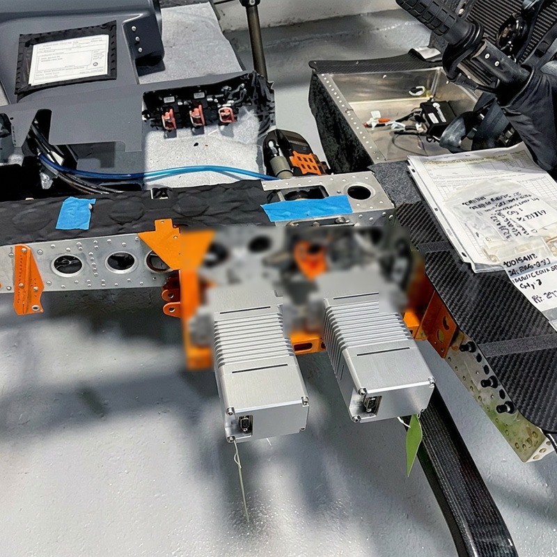
What Interference Does to a Servo PWM Signal
A standard servo PWM signal is a 1 to 2 millisecond pulse repeating every 20 milliseconds. The pulse width encodes the commanded position. If EMI couples onto the signal line during the pulse, the servo decodes the wrong width. A 1520-microsecond pulse with 30 microseconds of noise on the rising edge might read as 1550 microseconds — a 1.8-degree position error.
However, the real danger is not a single corrupted pulse. It’s periodic interference synchronized to the motor RPM. For example, a quadcopter motor running at 8000 RPM produces a 133 Hz fundamental. This creates a 133 Hz jitter on the servo position. The flight controller sees a 7.5-millisecond oscillation and interprets it as an attitude disturbance. Meanwhile, it’s just electrical noise on the signal wire.
How to Validate Your Servo’s EMI Hardening
Bench-test your servos before trusting them in the air. Power up the servo and command a static position. Then key up every transmitter on the aircraft at full power — telemetry, video, RC control — one at a time. Watch the servo output shaft with a magnifying glass or a laser pointer taped to the horn. Any visible twitch is a fail.
Next, run the motors at full throttle on the bench with the propellers off. Watch for position jitter synchronized to the motor RPM. If the servo moves at all during this test, your EMI RFI shielding is insufficient. Finally, repeat the test at your maximum intended operating range. RF coupling changes with distance. A servo that passes at 2 meters might fail at 200 meters when the signal-to-noise ratio at the receiver drops.xqservo.com1 EMI RFI shielding UAV servo