
XQ-POWER does not use one universal voltage range or one universal response-speed value across its servo portfolio. The correct range depends on the model and product variant. Published examples include the BLS8125D at 6.0–8.4 V, the S9150D at 8.4–16.8 V, the RS460 at a native 12 V input with an additional 9 V performance point, and the S9450D and S9750D high-voltage families with specifications reaching 30 V.
The speed shown on a product page is also model- and test-condition-specific. For example, the BLS8125D and RS8125D list 0.07 sec/60° at 8.4 V, the RS460 lists 0.14 sec/60° at 12 V, the S9150D lists 0.14 sec/60° at 16.8 V, the S9450D lists 0.21 sec/60° at 30 V, and the S9750D lists 0.25 sec/60° at 30 V.
These figures describe a specified or no-load movement condition—not the complete time from a controller decision to a loaded mechanism reaching its final position. Real response depends on voltage at the servo terminals, load torque, acceleration, command protocol, controller cycle, communication traffic, mechanical inertia, and the complete installation.
What working voltage range does each example model support?
The following table summarizes the voltage information available on the accessible product pages. Always use the current model-specific datasheet for a production design.
| Model | Published voltage information | Published speed point |
|---|---|---|
| BLS8125D | 6.0–8.4 V | 0.07 sec/60° at 8.4 V |
| RS8125D | 6.0–8.4 V | 0.07 sec/60° at 8.4 V |
| RS460 | 12 V native input; page also lists a 9 V performance point | 0.14 sec/60° at 12 V |
| S9150D | 8.4–16.8 V | 0.14 sec/60° at 16.8 V |
| S9450D | 24–30 V | 0.21 sec/60° at 30 V |
| S9750D | 24–30 V | 0.25 sec/60° at 30 V |
A “wide-voltage” description should therefore be read as a feature of a specific model or family, not as a claim that every XQ-POWER servo accepts the same supply. Applying the wrong voltage can damage the electronics, change the available torque, or produce behavior outside the published specification.
How fast does an XQ-POWER servo respond after a command?
The short answer is that several XQ-POWER models publish fast movement specifications, but the number on a datasheet is only one part of system response.
The BLS8125D and RS8125D list 0.07 sec/60° at 8.4 V. The RS460 lists 0.14 sec/60° at 12 V. The S9150D lists 0.14 sec/60° at 16.8 V. These values describe the time associated with a specified angular movement under the stated test condition.
They do not automatically mean that every control signal produces a complete mechanical movement in that same elapsed time. A real system also includes:
- Controller processing and command-update time
- PWM pulse timing or serial-bus frame transmission
- Bus scheduling and multi-device traffic
- Servo signal decoding and internal control-loop processing
- Motor acceleration and deceleration
- Load inertia and friction
- Mechanical compliance, backlash, and linkage movement
- Power-supply response under load
For this reason, “0.07 sec/60°” should not be rewritten as “0.07 seconds from software command to fully settled system position” unless that complete system has been measured under defined conditions.
What is the difference between operating voltage and test voltage?
A product’s operating-voltage range tells the engineer the supply interval for which the model is specified. A test-voltage value identifies the condition used for a particular torque or speed figure.
For example, the S9150D page lists an 8.4–16.8 V high-voltage range and gives its 0.14 sec/60° speed at 16.8 V. The BLS8125D page lists a 6.0–8.4 V range and gives 0.07 sec/60° at 8.4 V. The S9450D page lists 24–30 V and gives 0.21 sec/60° at 30 V.
The highest voltage point may produce a different speed or torque from a lower point. It should not be used to promise the same performance throughout the entire operating range. When selecting a servo, record the voltage required for the torque and speed you actually need.
Why can voltage fluctuation make a multi-servo system unstable?
In a multi-device system, the power supply and wiring must handle the combined electrical demand. Voltage at the power source is not necessarily the same as voltage at the servo terminals. Cable resistance, connector resistance, shared distribution, battery state, current peaks, and supply regulation can create a drop during acceleration or high-load holding.
A voltage disturbance can affect a system in several ways:
- The available motor torque may change.
- The measured movement speed may differ from the nominal test value.
- A controller or servo may reset or enter an abnormal state if its supply falls outside the required range.
- Several axes may respond differently when the shared supply is unevenly loaded.
- Communication hardware may behave differently if the servo or controller supply becomes unstable.
- Repeated current peaks can increase heat in the power distribution path.
A robust integration should measure voltage at the servo connector while the complete system is moving, not only at the bench power supply with no load.
How should engineers select a voltage for coordinated motion?
Start with the exact product variant and its specification. Then define the required torque, speed, operating cycle, and environmental conditions. A practical selection process is:
1. Confirm the model’s voltage range
Do not infer the range from another model, another communication version, or a product-family name. Use the exact datasheet or inspection specification for the selected model.
2. Match voltage to required torque and speed
Compare the published torque and speed at the voltage you intend to use. The BLS8125D, for example, lists torque values at 6.0 V, 7.4 V, and 8.4 V, while the S9150D lists torque points at 8.4 V, 12.6 V, and 16.8 V. Performance changes across those points.
3. Check supply capacity and voltage drop
Estimate the combined current demand of all devices and verify the supply, wiring, connectors, fusing, and distribution architecture. Measure the voltage at the farthest and most heavily loaded servo during acceleration and holding.
4. Review the command interface
Confirm whether the selected variant uses PWM, RS485, CAN, or another documented interface. A fast motor does not remove bus scheduling or controller-update delays.
5. Test the real load and motion profile
Measure time to reach the target position, overshoot, settling behavior, temperature, current, and supply voltage. Use the actual mechanism rather than an unloaded bench movement when response time is a system requirement.
How do the BLS8125D and RS8125D compare for response speed?
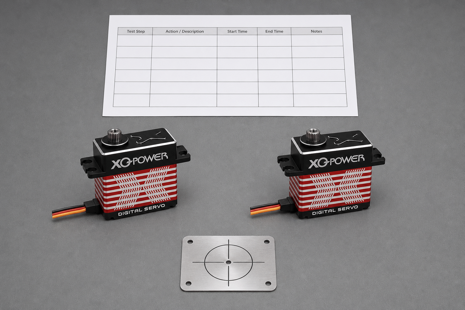
The BLS8125D brushless servo is listed with 6.0–8.4 V operation, 25 kg·cm torque at 8.4 V, and 0.07 sec/60° speed at 8.4 V. Its page describes a brushless motor, CNC aluminum case, toughened stainless-steel gears, and a splash-proof protection description.
The RS8125D RS485 brushless servo is also listed with 6.0–8.4 V operation, 25 kg·cm torque at 8.4 V, and 0.07 sec/60° speed at 8.4 V. Its distinguishing integration feature is the RS485 command-bus interface described on the page.
The two products should not be treated as interchangeable solely because their listed torque and speed points are similar. The control interface, wiring, protocol implementation, mechanical installation, firmware, and system architecture must match the application.
How does the RS460 support multi-device integration?
The RS460 Modbus RS485 smart robot servo is listed with 58 kg·cm torque at 12 V, 0.14 sec/60° speed at 12 V, and Modbus RS485 communication. The page also lists 360° absolute position control, up to 254 daisy-chained nodes, and feedback fields including position, temperature, speed, voltage, and current.
Those features can be useful when an integrator needs distributed motion control and monitoring. They do not eliminate the need to design the power network. A daisy-chained communication bus and a shared power bus are separate engineering concerns: communication wiring does not guarantee uniform voltage at every actuator.
For a multi-axis robot, record the bus update cycle and the supply voltage at each critical node. Then test simultaneous acceleration and holding, because those conditions can expose voltage drop that is not visible during single-axis movement.
How do high-voltage models behave in industrial applications?
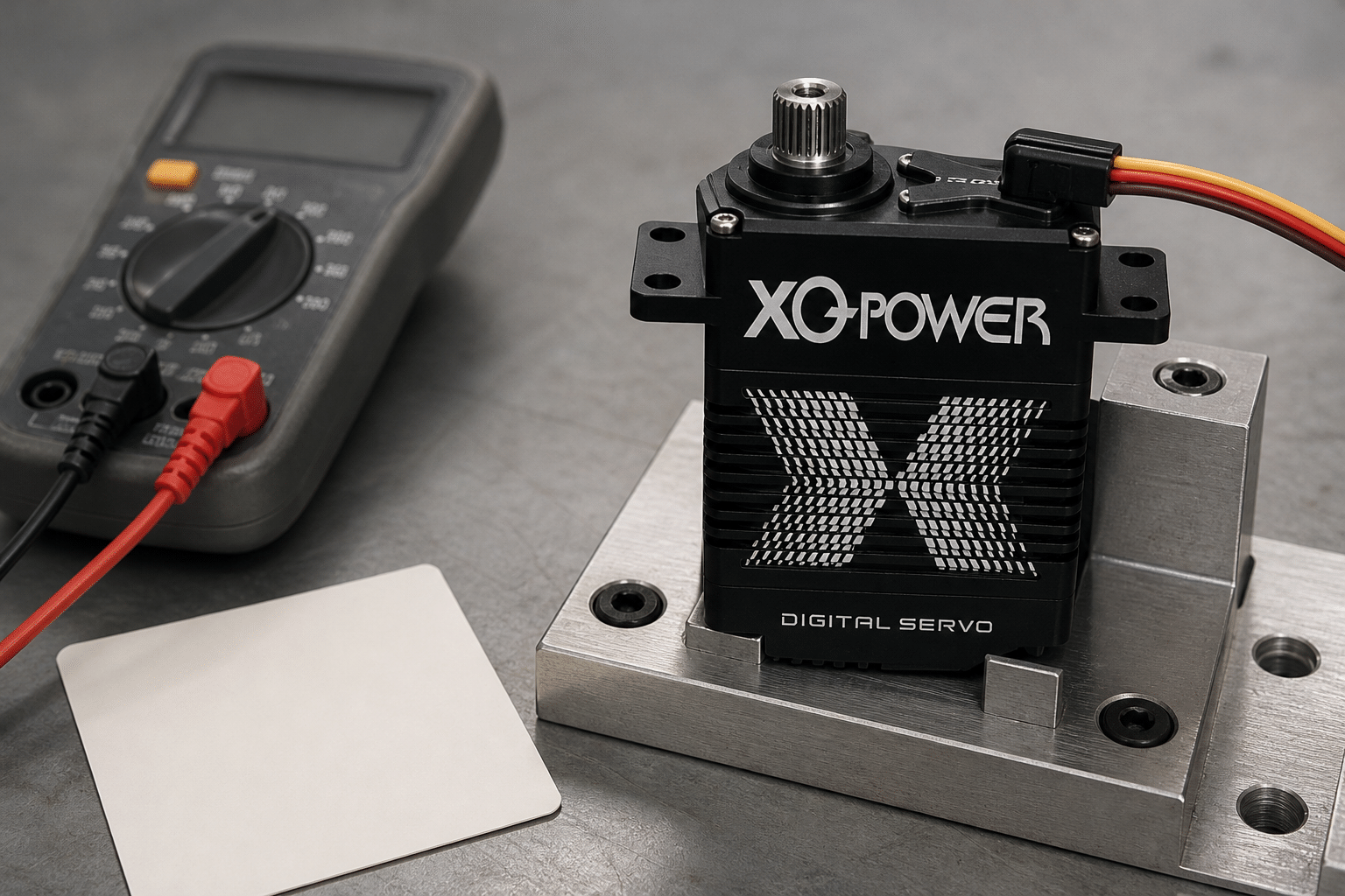
The S9150D 180 kg industrial brushless servo is listed with 8.4–16.8 V operation, 180 kg·cm peak stall torque at 16.8 V, and 0.14 sec/60° speed at 16.8 V. The page identifies applications including robotic joints and AGVs.
The S9450D 700 kg·cm-class servo is listed with 24–30 V operation and 0.21 sec/60° no-load speed at 30 V. The page records 560 kg·cm at 24 V, 650 kg·cm at 28 V, and 700 kg·cm at 30 V as peak stall torque points.
The S9750D 1000 kg·cm-class servo is listed with 24–30 V operation and 0.25 sec/60° no-load speed at 30 V. Its inspection values record 850 kg·cm at 24 V, 920 kg·cm at 28 V, and 980 kg·cm at 30 V as peak stall torque points.
These examples show why voltage, torque, and speed must be read together. The higher-voltage model is not automatically the fastest for every load, and the highest torque point is not automatically a continuous operating condition.
How should signal latency be measured?
A useful response-time test should define where the timer starts and where it stops. For example:
- Start point: the controller creates a command, sends a PWM pulse, or begins a bus frame.
- Signal-transfer interval: the command travels through the controller, cable, transceiver, and bus schedule.
- Servo-processing interval: the servo decodes the command and updates its internal control loop.
- Mechanical interval: the motor accelerates the load and the output moves.
- End point: the output reaches the defined position window and remains within that window.
A product’s no-load speed is not the same measurement as a complete closed-loop settling time. If the application requires coordinated motion, define a measurable position window, load, allowed overshoot, update period, and voltage condition before comparing products.
How can supply stability be improved during integration?
The exact power design depends on the system, but engineers should review:
- Supply rating for the combined continuous and transient load
- Voltage drop across the longest cable and connectors
- Separate or well-designed power distribution for high-current axes
- Grounding and signal-return strategy
- Connector current rating and mechanical retention
- Protection against reverse polarity and wiring faults where applicable
- Battery state and regulator behavior in mobile platforms
- Voltage measurement at the servo under the real load
- Thermal behavior of the power supply and distribution components
Do not solve every instability by simply increasing nominal voltage. The selected voltage must remain within the model’s specified range, and the controller, wiring, connectors, and other devices must be compatible with it.
The XQ-POWER Technical Guide covers servo sizing, protocol selection, and thermal management under real loads. For a model-specific selection, provide the complete application conditions to the engineering team.
What should be included in an XQ-POWER technical inquiry?
For a coordinated-motion project, include:
- Servo model and exact variant
- Required supply voltage and acceptable tolerance
- Number of simultaneous servo axes
- Continuous and peak torque
- Required movement angle and target response time
- Load inertia, acceleration, and duty cycle
- Control interface: PWM, RS485, CAN, or another documented option
- Cable length, connector arrangement, and power-distribution plan
- Operating temperature and environmental conditions
- Required position-error and settling limits
This information allows XQ-POWER to recommend a suitable standard product, sample test, or OEM/ODM solution without assuming that one voltage or one speed value applies to the whole portfolio.
Servo Voltage Range and Response Speed FAQ
The range depends on the model. Published examples include 6.0–8.4 V for the BLS8125D and RS8125D, 8.4–16.8 V for the S9150D, 12 V native input for the RS460, and 24–30 V for the S9450D and S9750D high-voltage families. Confirm the exact product variant before connecting a power supply.
Published movement-speed examples include 0.07 sec/60° for the BLS8125D and RS8125D at 8.4 V, 0.14 sec/60° for the RS460 at 12 V, 0.14 sec/60° for the S9150D at 16.8 V, 0.21 sec/60° for the S9450D at 30 V, and 0.25 sec/60° for the S9750D at 30 V. These are model- and condition-specific movement figures, not universal end-to-end system latency.
No. A higher voltage may change the speed and torque available within the model’s specified range, but the result depends on the motor, drive, load, controller, and test condition. Never exceed the model’s voltage limit, and compare speed data at the same defined test conditions.
Voltage drop can reduce available torque, change movement speed, cause resets, or make different axes behave differently during simultaneous acceleration and holding. Measure voltage at the servo connector under the real load rather than checking only the unloaded power-supply output.
Both product pages list 0.07 sec/60° at 8.4 V and 6.0–8.4 V operation. However, they use different integration approaches: the RS8125D page identifies RS485 command-bus control, while the BLS8125D page describes a high-performance brushless servo. The exact controller, protocol, load, and installation determine system-level response.
No. Coordinated motion also depends on controller cycle time, communication traffic, bus scheduling, signal transfer, servo processing, acceleration, load inertia, power stability, mechanical compliance, and settling requirements. Measure complete system response with the actual axes and load.
Need help selecting a servo voltage and response profile?
Share the required voltage, torque, speed, number of axes, control interface, load profile, cable arrangement, and response-time target with the XQ-POWER engineering team. The team can help evaluate a standard model, sample test, or OEM/ODM motion-control requirement.