
XQ-POWER’s published high-torque servo range reaches the 1000 kg·cm class. The exact torque depends on the model, supply voltage, test condition, and selected product variant. For example, the website lists the S9150D at 180 kg·cm, the S9450D at 700 kg·cm class, and the S9750D at 1000 kg·cm class.
These figures are not interchangeable with a continuous-load rating. For a robot joint, crawler vehicle, off-road mechanism, or small robotic arm, the correct question is not only “What is the biggest torque number?” It is also “What torque is required continuously, for how long, at what voltage, speed, duty cycle, temperature, and mechanical leverage?”
A servo is also not normally described as “losing steps” in the same way as an open-loop stepper motor. A closed-loop servo continuously controls position, but it can still experience position error, drift, reduced holding performance, gear damage, or thermal protection when the applied load exceeds the verified operating conditions. The practical rule is to keep the application within the model’s confirmed load and duty-cycle range, then validate the real mechanism.
How much torque can an XQ-POWER servo provide?
The answer depends on the product family and the voltage condition shown in the specification. The following examples are taken from accessible XQ-POWER product pages:
| Model | Published torque information | Important condition |
|---|---|---|
| S9150D | 180 kg·cm at 16.8 V; 160 kg·cm at 12.6 V; 115 kg·cm at 8.4 V | The page identifies the 180 kg·cm figure as peak stall torque at 16.8 V |
| S9450D | 560 kg·cm at 24 V; 650 kg·cm at 28 V; 700 kg·cm at 30 V | The inspection specification records peak stall torque at the listed voltages |
| S9750D | 850 kg·cm at 24 V; 920 kg·cm at 28 V; 980 kg·cm at 30 V | The product is presented as a 1000 kg·cm-class servo; the inspection values are peak stall torque under the listed conditions |
| RS460 | 58 kg·cm at 12 V | Integrated Modbus RS485 smart servo with position, temperature, speed, voltage, and current feedback listed on the page |
The XQ-POWER High Torque Servo category provides the product-family overview. Always use the current model-specific datasheet or inspection specification for final design decisions.
Why the maximum torque number is not a continuous rating
A maximum, peak, or stall torque value is measured under a defined test condition. It indicates what the servo produced at that test point; it does not automatically establish how long the servo can hold that load or repeat it safely.
Continuous performance depends on several interacting variables:
- Supply voltage at the servo under load
- Required output torque and direction
- Operating speed and acceleration
- Load inertia and mechanical leverage
- Motion cycle, load duration, and rest interval
- Ambient temperature and heat dissipation
- Mounting stiffness and output-shaft loading
- Gear-train losses, friction, and mechanical compliance
- Controller settings and feedback behavior
The stall torque versus continuous torque guide explains why a high peak number should not be used as a continuous operating guarantee.
Will an XQ-POWER servo lose steps under a heavy load?
Strictly speaking, “lost steps” is usually associated with an open-loop stepper system, where the controller assumes that the motor followed the commanded steps without receiving direct confirmation of the actual position. A servo uses feedback to control its output position, so the more precise engineering questions are:
- Does the output remain within the required position error?
- Does the servo maintain the commanded position under the actual load?
- Does the controller report an error or abnormal condition?
- Does the gear train remain within its mechanical load limit?
- Does heat build up during repeated or sustained torque production?
Within the model’s verified operating range, correct voltage, suitable mounting, and a properly configured control system, XQ-POWER servo products are intended for controlled positioning and torque output. However, no general statement should be extended into an absolute guarantee for every model, load, duty cycle, or installation.
If the applied load exceeds the verified capability, the output may not maintain the commanded position. Depending on the mechanism and failure mode, the result may appear as position error, drift, delayed recovery, increased current, audible noise, thermal protection, gear backlash, or mechanical damage.
What happens when the load exceeds the servo limit?
Long-term operation beyond the specified or validated load can create several risks:
- Motor and driver heating: Sustained high current increases heat generation. Temperature rise depends on torque, speed, duty cycle, voltage, mounting, and cooling.
- Gear-train stress: The gears and output structure must transmit the reaction torque. Shock loads and repeated impacts can be more damaging than a smooth static load.
- Position error: When the mechanism cannot produce enough output torque, it may fail to hold the commanded position or may recover slowly after the load changes.
- Backlash or mechanical wear: Repeated overload can increase play in the transmission and reduce positioning repeatability.
- Structural and output-interface stress: A bracket, spline, horn, shaft, or linkage can fail even when the servo itself has a high torque label.
- Reduced service life: Operating at or beyond a peak test point for long periods can accelerate wear and thermal degradation.
For these reasons, the recommended operating point should be based on the confirmed load profile rather than the largest number printed in a product title.
How the S9150D supports heavy-load evaluation
The S9150D 180 kg industrial brushless servo is listed with 180 kg·cm peak stall torque at 16.8 V, 0.14 sec/60° speed at 16.8 V, an 8.4–16.8 V voltage range, a CNC aluminum case, toughened steel gears, and a 25T output with a 9.95 mm diameter.
The page also presents the S9150D for applications including heavy-duty robotic arms and warehouse AGVs, and links to a 2000-hour endurance test report. These published details make the model relevant for heavy-load evaluation, but they do not eliminate the need to match the actual torque, duty cycle, temperature, mounting, and transmission conditions.
A robot or AGV integrator should validate the joint or steering mechanism rather than relying on a static stall test alone.
How the S9450D and S9750D fit higher-torque applications
The S9450D 700 kg·cm-class industrial servo is listed with peak stall torque of 560 kg·cm at 24 V, 650 kg·cm at 28 V, and 700 kg·cm at 30 V. The product page identifies steel gearing, an aluminum CNC case, eight ball bearings, and a 25T output specification.
The S9750D 1000 kg·cm-class industrial servo is listed with peak stall torque of 850 kg·cm at 24 V, 920 kg·cm at 28 V, and 980 kg·cm at 30 V. The page identifies a high-output industrial platform, steel gearing, an aluminum CNC case, ten ball bearings, and a 25T output specification.
The S9750D product title uses the 1000 kg·cm class, while the accessible inspection values list 980 kg·cm at 30 V. These should not be silently treated as the same measurement. When a project needs a precise maximum or continuous value, request the model-specific specification, test conditions, and duty-cycle definition from XQ-POWER.
How to choose torque for a crawler, off-road robot, or robotic arm
A heavy crawler or off-road robot may experience steering resistance, impact loads, traction changes, and shock loads transmitted through the wheels or suspension. A robotic arm may experience a changing lever arm as the joint moves. A small robotic arm can therefore require more torque in one posture than another, even when its payload remains unchanged.
Use this selection sequence:
1. Calculate the output load
Estimate the force at the output and multiply it by the effective lever arm. Include the mechanism’s own weight, payload, friction, acceleration, and transmission efficiency.
2. Separate continuous and peak requirements
Record the torque needed during normal movement, the torque needed during acceleration, and the highest short-duration shock or peak event. Do not use the stall value as the continuous target.
3. Check the power system
Confirm that the power supply, wiring, connectors, and protection devices can deliver the required voltage and current at the servo under load. A voltage drop can reduce the available torque and change the thermal condition.
4. Check the mechanical interface
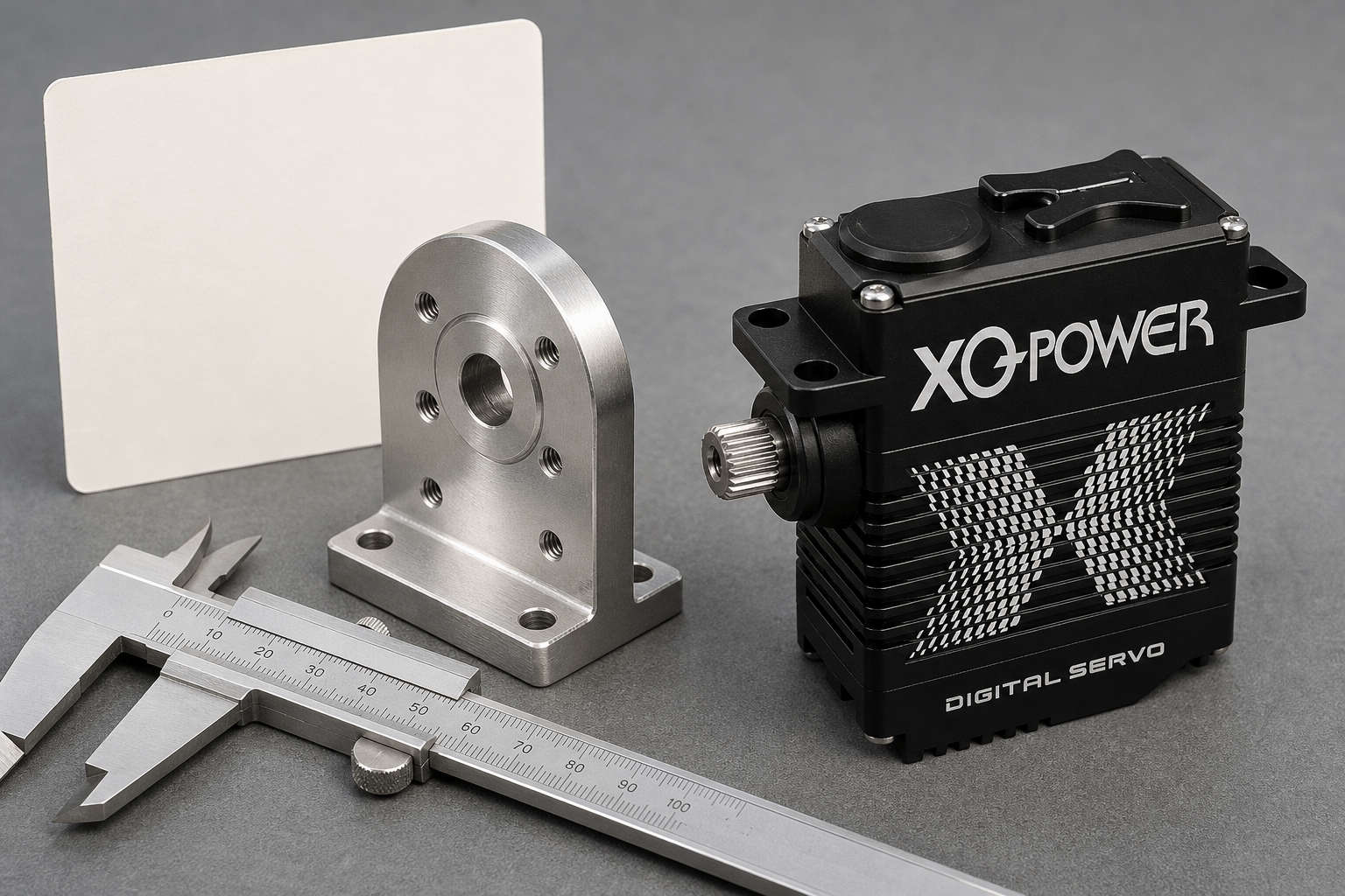
Verify mounting stiffness, output spline, shaft or horn compatibility, linkage alignment, radial and axial loading, and clearance throughout the complete movement. The servo mounting guide covers these mechanical considerations.
5. Test the complete duty cycle
Run the real movement sequence with the actual load, speed, acceleration, rest interval, mounting, and environmental conditions. Record position error, current, temperature, noise, vibration, and any change in gear play.
Why gear and output-shaft strength matters
High torque is transmitted through the entire mechanical path. The motor, gearbox, bearings, output shaft, spline, horn, bracket, and driven mechanism all contribute to the result.
A larger output shaft or stronger gear structure can help a product handle demanding mechanical loads, but it does not override the model’s specified conditions. The mounting structure must also resist the reaction torque. A stiff servo mounted to a flexible bracket can still show position error or vibration because the system, not just the actuator, is moving.
For a robot joint or crawler steering system, inspect the output interface after sample testing. Check for unusual play, deformation, surface damage, loose fasteners, or changes in the neutral position.
How to validate position holding under heavy load
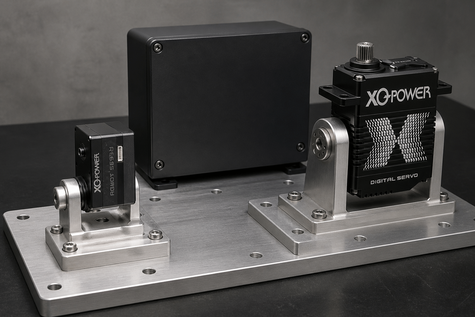
A practical heavy-load validation test should include:
- The exact servo model and product variant
- Supply voltage measured at the servo terminals
- Static holding torque and moving torque
- Load direction and lever arm
- Motion speed and acceleration
- Duty cycle and rest interval
- Ambient and case temperature
- Position command and measured output position
- Mechanical mounting and linkage configuration
- Current, vibration, noise, and gear-play observations
- Pass/fail limits for position error and temperature
Do not evaluate only one unloaded movement. A servo may appear precise without load but behave differently when it holds torque, reverses direction, or repeats a high-load cycle.
If the application requires a serial-bus actuator with feedback, the RS460 Modbus RS485 smart robot servo lists position, temperature, speed, voltage, and current feedback. These fields can support system monitoring when the controller, firmware, and communication implementation are correctly matched.
A practical answer for project teams
For an initial project discussion, the answer can be summarized as follows:
- XQ-POWER offers high-torque products up to the 1000 kg·cm class.
- The exact maximum depends on the model and test voltage; the S9750D page lists 980 kg·cm peak stall torque at 30 V, while the product is described as 1000 kg·cm class.
- S9450D and S9150D provide lower high-torque classes with their own voltage-dependent values.
- A servo should not be judged by stall torque alone.
- A servo is not expected to “lose steps” in the same open-loop sense as a stepper, but an overloaded or overheated servo can develop position error, drift, gear wear, or mechanical damage.
- Keep the selected model within its confirmed load and duty-cycle range, and validate it on the real mechanism.
Maximum Servo Torque and Heavy-Load FAQ
XQ-POWER’s published range reaches the 1000 kg·cm class. The S9750D page lists peak stall torque of 850 kg·cm at 24 V, 920 kg·cm at 28 V, and 980 kg·cm at 30 V. Because the product is described as 1000 kg·cm class, the exact maximum should be specified using the current model-specific inspection document and test conditions.
The S9450D inspection specification lists peak stall torque of 560 kg·cm at 24 V, 650 kg·cm at 28 V, and 700 kg·cm at 30 V. These are voltage-dependent peak stall values and should not automatically be treated as continuous operating torque.
The S9150D page lists 180 kg·cm at 16.8 V, 160 kg·cm at 12.6 V, and 115 kg·cm at 8.4 V. The 180 kg·cm value is identified as peak stall torque at 16.8 V. Select the model according to the complete load profile and duty cycle.
A servo is not normally described as losing steps in the same way as an open-loop stepper motor because it uses position feedback. However, if the load exceeds the verified capability or the servo overheats, the output can develop position error, drift, delayed recovery, gear wear, or mechanical damage. Heavy-load performance must be validated under the actual operating conditions.
Not automatically. A peak or stall torque value is measured at a defined test point. Continuous holding depends on voltage, speed, duty cycle, load duration, ambient temperature, mounting, cooling, transmission losses, and the model-specific thermal and mechanical limits.
The suitable model depends on the required torque, speed, voltage, load inertia, mechanical envelope, duty cycle, interface, and environmental conditions. XQ-POWER publishes products such as the 25 kg·cm BLS8125D, 58 kg·cm RS460, 180 kg·cm S9150D, 700 kg·cm-class S9450D, and 1000 kg·cm-class S9750D. These product values are not interchangeable; request engineering confirmation for the actual application.
Need help selecting a heavy-load servo?
Share the required torque, voltage, speed, duty cycle, load profile, mounting arrangement, output interface, operating environment, and position-holding limits with the XQ-POWER engineering team. The team can review a standard model, sample-validation plan, or OEM/ODM requirement for a robot, crawler, AGV, robotic arm, or other heavy-load mechanism.