
The output shaft is a critical part of the torque path between a servo and the mechanism it drives. However, output-shaft reliability is not determined by shaft material alone. Spline geometry, engagement depth, horn or hub fit, retaining hardware, alignment, external radial load, bending moment, repeated impact, temperature, surface condition, and the actual duty cycle all affect whether a connection remains secure.
The short answer is precise: XQ-POWER product pages publish the output-shaft or spline dimensions for selected models, but the pages reviewed do not establish one output-shaft material for every servo in the product range. The pages do identify metal gear trains and model-specific output interfaces. Before specifying a shaft material for a production design, confirm the exact model, variant, datasheet, and engineering response.
When a servo is correctly installed and operated inside its validated mechanical and electrical limits, frequent motion does not automatically mean that the shaft will slip or break. It is still necessary to verify the shaft-to-horn connection, load direction, shock profile, and fatigue life for the real application.
What can make a servo output connection slip?
“Slip” can describe several different failures. The output shaft itself may not be the part that loses position. Common interfaces and failure points include:
- Spline-to-horn mismatch: The tooth count, profile, engagement depth, or mating component may not match the servo output.
- Insufficient fastener retention: A retaining screw, clamp, nut, or washer may loosen under vibration or repeated reversal.
- Poor seating: A horn or hub may not be fully seated against the output face.
- Excessive backlash or wear: Repeated motion can increase clearance in the spline, horn, linkage, or driven mechanism.
- Overload or shock: A sudden torque spike can deform the mating interface or damage the first loaded teeth.
- Misalignment: A coupling or linkage that is not aligned can add radial load, friction, and bending to the output assembly.
- External structure movement: A flexible bracket or loose mounting plate can move even when the servo shaft is holding its commanded position.
For troubleshooting, mark the horn, shaft, and driven component with a reference line before testing. After a controlled motion cycle, compare the marks and inspect the fastener, spline teeth, mounting face, and linkage. This helps distinguish interface slip from servo-control error, gear backlash, bracket movement, or external load deflection.
Can frequent oscillation cause a shaft to break?
Frequent oscillation does not automatically cause output-shaft breakage. The risk depends on the torque amplitude, reversal frequency, external bending moment, radial and axial loads, impact duration, temperature, surface condition, alignment, and number of cycles.
A low-load oscillation test and a high-load impact test are not equivalent. A mechanism may complete millions of small movements but fail quickly if a hard stop or collision creates a large transient torque. Conversely, an occasional load near the peak rating may be less damaging than a high-frequency cycle that repeatedly exceeds the validated fatigue envelope.
The correct question is not simply “Can this shaft move back and forth?” It is:
- What torque reaches the output interface during acceleration and reversal?
- What radial and axial forces act on the shaft?
- Is the driven part cantilevered away from the servo?
- How much external bending moment is applied?
- How many cycles are required?
- Are there hard stops, collisions, or landing impacts?
- Does the connection remain tight and aligned at the operating temperature?
- Has the exact assembly been tested with the real load?
How are shaft strength, spline strength, and gear strength different?
Output-shaft strength
The shaft transfers rotary torque and may also be exposed to external radial, axial, or bending loads. A shaft can remain visually intact while its bearing support, spline root, or mating interface is overloaded.
Spline and horn strength
The spline transfers torque through the engaged teeth. Tooth geometry, contact area, engagement depth, material pairing, fit, and retaining hardware affect the connection. A slip event may result from the horn or fastener before the shaft material reaches its failure limit.
Gear-train strength
The internal gears transmit motor torque to the output. Peak or stall torque is not automatically a continuous-duty rating. Repeated overload can produce tooth wear, pitting, deformation, or fracture even when the output shaft appears undamaged.
Housing and bearing support
The housing and bearings maintain alignment and support the output assembly. External bending or a misaligned load can increase bearing stress and shaft deflection, changing the loads seen by the gears and spline.
This is why a product’s torque label cannot be used alone to predict shaft reliability in a robot arm, crawler, or automated mechanism.
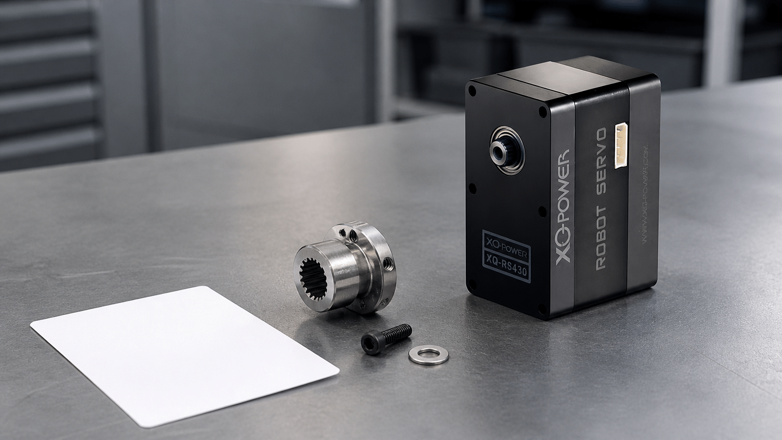
What output-interface information is available for selected XQ-POWER models?
The accessible product pages provide useful model-specific interface information, but they should not be generalized to every model:
| Model | Published output/interface information | Other published structural information | What still requires confirmation |
|---|---|---|---|
| RS460 | Heavy-duty output shaft, 8 mm diameter | Toughened-steel gear train; dual industrial ball bearings | Shaft material, allowable radial/axial load, fatigue limit, mating-hub requirements |
| S9150D | 25T output specification, 9.95 mm diameter | Toughened-steel gear; CNC aluminum case | Shaft material, allowable external load, spline engagement and fatigue data |
| S9450D | 25T output specification, 11.98 mm diameter | Steel gear; eight ball bearings; aluminum CNC case | Shaft material, external-load limits, duty-cycle and fatigue data |
| S9750D | 25T output specification, 14.98 mm diameter | Steel gear; ten ball bearings; CNC aluminum case | Shaft material, external-load limits, duty-cycle and fatigue data |
| BLS8125D | Output geometry should be checked in the applicable specification | Toughened stainless-steel gear set; CNC aluminum case | Output-shaft material and allowable external loading |
The dimensions and materials shown in this table are not interchangeable. Always use the datasheet for the exact model and variant before machining a mating part or approving a production design.
How should a servo be installed to reduce slip risk?
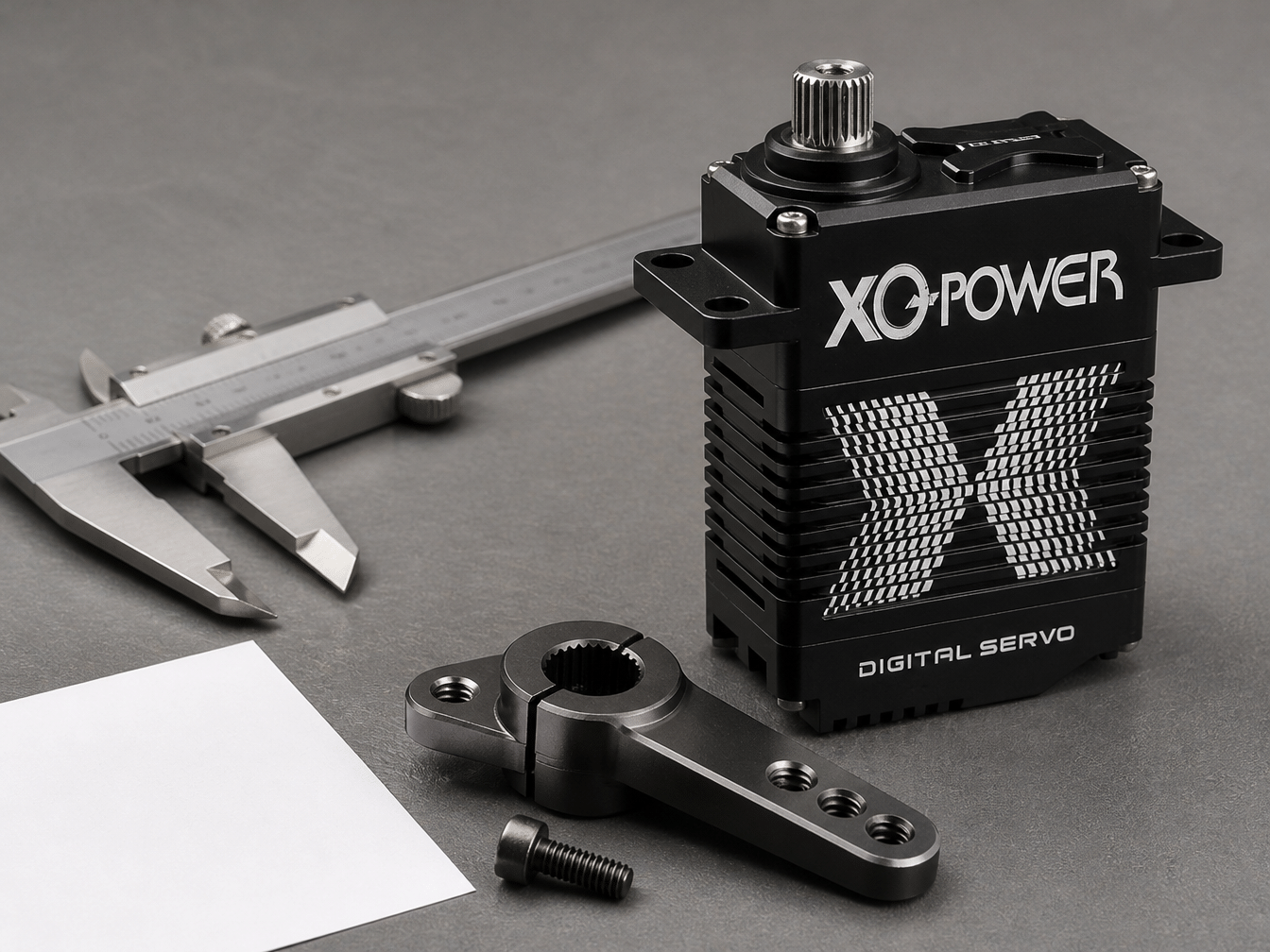
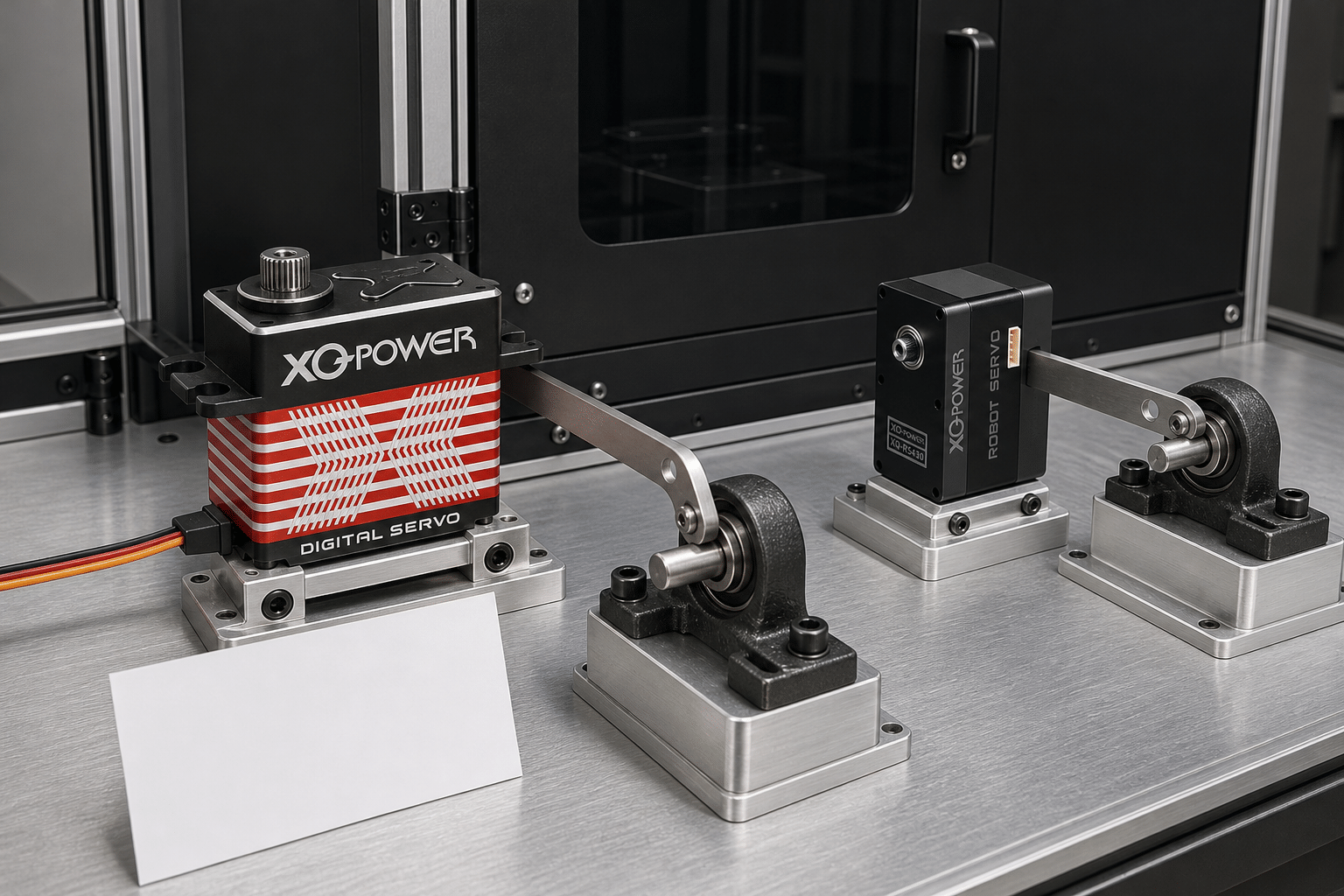
The XQ-POWER mounting guide recommends treating the servo, mounting plate, coupling, linkage, and driven shaft as one mechanical system. Apply the same principle to output-shaft reliability.
Match the mating interface
Confirm spline tooth count, geometry, engagement depth, shaft diameter, horn or hub compatibility, and retaining hardware. Do not assume that two visually similar servos share the same output interface.
Fully seat the horn or hub
The mating part should sit squarely on the output interface with the required engagement. Avoid partial engagement, side loading during installation, or a horn that bottoms on the fastener before it seats on the shaft.
Control fastener retention
Use the fastener type, tightening method, thread engagement, washer, locking feature, and maintenance procedure specified for the assembly. Do not rely on friction alone where repeated reversal and vibration can loosen the connection.
Avoid unapproved external loads
If the driven mechanism places a large radial, axial, or bending load on the output, use an independent shaft, bearing, hub support, or linkage arrangement so the servo is primarily responsible for driving torque rather than carrying the entire structural load.
Maintain alignment
Misalignment can produce side force, bearing stress, friction, vibration, and spline wear. Check alignment through the full range of motion, not only at the neutral position.
Provide mechanical stops carefully
A hard stop can convert motion energy into a high transient torque. If stops are required, evaluate their position, compliance, impact duration, and repetition rate during testing.
How should frequent oscillation be validated?
A useful validation plan should reproduce the real mechanism rather than only rotating the servo without a load. Record:
- Exact servo model and variant
- Supply voltage and voltage variation
- Load torque throughout the motion
- External radial, axial, and bending loads
- Oscillation angle, speed, acceleration, and reversal rate
- Number of cycles and rest periods
- Ambient and case temperature
- Horn, hub, fastener, and spline condition before and after testing
- Position error, backlash, and any visible movement at the mounting structure
- Current, overload, reset, or protection events where available
Use a guarded test fixture for shock or high-load tests. Stop the test if the output interface develops visible play, the reference marks move, the temperature exceeds the approved limit, or the mechanism begins to bind.
A production approval should be based on documented test conditions and acceptance criteria, not on a general statement that a shaft is “strong enough.”
What are the signs of shaft, spline, or mounting damage?
Inspect the complete torque path when any of the following appears:
- The commanded position and mechanism position no longer agree.
- A reference mark on the horn moves relative to the output shaft.
- Backlash increases after repeated cycles.
- The horn or hub rocks on the output interface.
- Spline teeth show polishing, deformation, burrs, or missing material.
- The retaining fastener loosens repeatedly.
- The output shaft develops visible runout or unusual radial movement.
- The housing, mounting ears, or plate show cracks or permanent deformation.
- The servo becomes noisy, hot, or mechanically rough.
- Position error appears only during acceleration, reversal, or impact.
Do not continue cycling a suspected damaged assembly at full load. Remove the load, document the condition, and request model-specific engineering guidance.
Does operating inside the rated torque range guarantee no slip or breakage?
No. Operating inside a published torque point is important, but it does not by itself guarantee that every installation will avoid slip or breakage. The published torque may be a peak or stall value under a defined voltage and test condition, while the application may add external bending, radial load, impact, misalignment, friction, or repeated fatigue cycles.
The high-torque sizing guide explains why stall torque and continuous torque must be treated differently. For a production mechanism, confirm the duty cycle, load path, external shaft loading, thermal condition, interface fit, and required service life.
What should be confirmed with XQ-POWER before a production design?
Provide the following information when asking about output-shaft reliability:
- Exact model and product variant
- Output spline or shaft dimensions required by the design
- Driven load, lever arm, and calculated torque
- Radial, axial, and bending loads at the output
- Oscillation angle, speed, acceleration, and cycle count
- Shock, collision, hard-stop, or landing conditions
- Horn, hub, coupling, fastener, and bearing arrangement
- Operating voltage, temperature, and environmental conditions
- Required service life and acceptable backlash or position error
- Prototype test results and any observed damage
For model-specific material confirmation, allowable external load data, sample testing, or OEM/ODM engineering support, use the XQ-POWER contact page.
Practical checklist for output-shaft reliability
- The output-shaft material is verified for the exact model if material is a design requirement.
- The spline or shaft geometry matches the horn, hub, or coupling.
- The mating part is fully seated and adequately retained.
- External radial, axial, and bending loads are quantified.
- The servo is not being used as the only structural bearing for a cantilevered load.
- Acceleration, reversal, hard-stop, and shock loads are included in the calculation.
- Peak/stall torque is not confused with continuous operating torque.
- Alignment and mounting stiffness are checked through the full motion range.
- Reference marks, backlash, temperature, current, and position error are monitored.
- The exact assembly has passed a guarded, documented endurance test.
Frequently Asked Questions
Servo Output Shaft Material and Reliability FAQ
Need help confirming an output shaft or spline for your application? Send the exact model, required shaft or spline interface, torque and external-load conditions, cycle profile, mounting design, and test target to the XQ-POWER engineering team. The team can review model-specific output details, sample testing, and OEM/ODM requirements.
The accessible XQ-POWER product pages reviewed for this article publish output-shaft geometry for selected models and separately describe materials such as steel gears, toughened-steel gear trains, stainless-steel gear sets, and aluminum cases. They do not establish one output-shaft material for the complete product range. Confirm the shaft material and any heat-treatment or hardness requirement for the exact model with the current datasheet or XQ-POWER engineering team.
Frequent oscillation does not automatically cause slip. Slip can occur when the spline and horn do not match, the mating part is not fully seated, the retaining fastener loosens, the interface is worn, or shock and external loads exceed the validated mechanical condition. Inspect and mark the shaft-to-horn connection during endurance testing.
Any mechanical output can be damaged if the shaft, spline, bearings, gears, housing, or mating components are subjected to excessive torque, bending, radial load, axial load, impact, or fatigue. The correct evaluation requires the exact model, load path, duty cycle, shock profile, alignment, and documented test results.
No. A published torque value describes the servo’s output under a defined test condition; it does not by itself specify the allowable external bending moment, radial load, axial load, spline fatigue life, or continuous-duty limit. Confirm these requirements separately for the selected model and mechanism.
Match the output interface, use sufficient spline engagement, seat the horn or hub squarely, apply the specified retaining method, maintain alignment, prevent unapproved side loads, and inspect the connection after controlled load cycles. An independent bearing or shaft support can reduce the external load carried by the servo output.
Test the exact servo and mechanism with the real torque, lever arm, oscillation rate, acceleration, reversal, impact, temperature, and cycle count. Monitor reference marks, backlash, position error, output runout, fastener retention, current, and temperature. Include hard stops or shock events if they exist in the real application.