
Yes, it can. At low temperature, lubricant viscosity may increase, gear and bearing resistance may rise, and the driven mechanism may require more breakaway torque. The motor can therefore draw a higher transient current during startup than it draws after reaching motion. At high altitude, the electrical and thermal environment may also change because of power-source behavior, cable losses, reduced air density, and the application’s reduced heat-transfer capability.
The practical answer for an XQ-POWER application is conditional: a higher cold-start current is possible, but the actual value and whether the driver board can tolerate it depend on the exact servo model, driver design, supply, load, temperature, altitude, duty cycle, and protection settings. The accessible XQ-POWER pages do not publish one universal cold-start current or one driver-board current rating for the full product range.
A production decision should therefore be based on a controlled environmental test rather than on a room-temperature no-load measurement or a product-title torque value.
Why can low temperature increase startup current?
A servo normally experiences a short acceleration interval when its motor starts moving. During this interval, current is influenced by required torque, motor characteristics, supply voltage, controller behavior, and mechanical resistance.
- Lubricant viscosity can rise. Grease or oil may become less mobile, increasing resistance in gears, bearings, seals, or sliding interfaces.
- Breakaway torque can increase. A mechanism may require more torque to start from rest than to continue moving.
- Materials can contract. Changes in clearance or fit can affect gears, bearings, seals, and couplings.
- The external load can change. A frozen, stiff, contracted, or contaminated mechanism may add resistance.
- The power source can behave differently. Battery voltage, regulator output, and available current may change with temperature.
- The high-current acceleration state may last longer. Slow acceleration can extend the transient event even when running current is acceptable.
These mechanisms do not prove a specific current increase for every model. A cold-start test must use the real mechanism, supply, cable, and load rather than a free-running servo alone.
Is startup current the same as stall current?
No. Startup or inrush current is drawn while the motor accelerates from rest; running current is measured after reaching the defined motion state; peak or transient current is a short event during acceleration, reversal, correction, or impact; stall current is measured when the output is prevented from rotating under a defined condition; and driver-board current margin is the electrical and thermal capacity of the driver stage and its protection system.
A cold start may approach a high-current condition if the mechanism does not move promptly, but it should not automatically be labeled as the model’s stall current. The current waveform and duration matter. A short peak and a prolonged near-stall event impose different stresses on the motor, MOSFETs, PCB traces, connectors, supply, and protection components.
What does the XQ-POWER public data show?
The accessible product pages provide useful model-specific reference points, but they do not provide a universal cold-start specification.
S9150D
S9150D industrial brushless servo is published with an 8.4–16.8 V voltage range, 180 kg·cm peak stall torque at 16.8 V, 0.14 sec/60° no-load speed at 16.8 V, and a 10.0 A stall-current point at 16.8 V. The page also identifies a CNC aluminum case and steel gear train.
The 10.0 A value is a specified stall-current point under the listed condition. It is not a cold-start current, a driver-board rating, or a universal continuous-current requirement. A cold environmental test must measure the actual current waveform at the selected voltage, load, and temperature.
S9450D
S9450D industrial servo lists 24–30 V operation, no-load current points of 400 mA at 24 V, 430 mA at 28 V, and 450 mA at 30 V, and stall-current points of 18 A, 21 A, and 22.5 A at those voltages. These values describe listed test conditions and do not define cold-start current or internal driver-board margin.
The same page lists an operating temperature range of -30°C to +60°C and storage range of -30°C to +70°C. These model-specific values do not establish a high-altitude rating, cold-start performance, or UAV suitability without a system test.
S9750D
S9750D industrial servo lists 24–30 V operation, no-load current points of 400 mA, 460 mA, and 500 mA, and stall-current points of 21 A, 25 A, and 26.5 A at 24 V, 28 V, and 30 V. These are model-specific reference points, not cold-start measurements; no specific altitude limit or cold-start current curve is published.
RS460
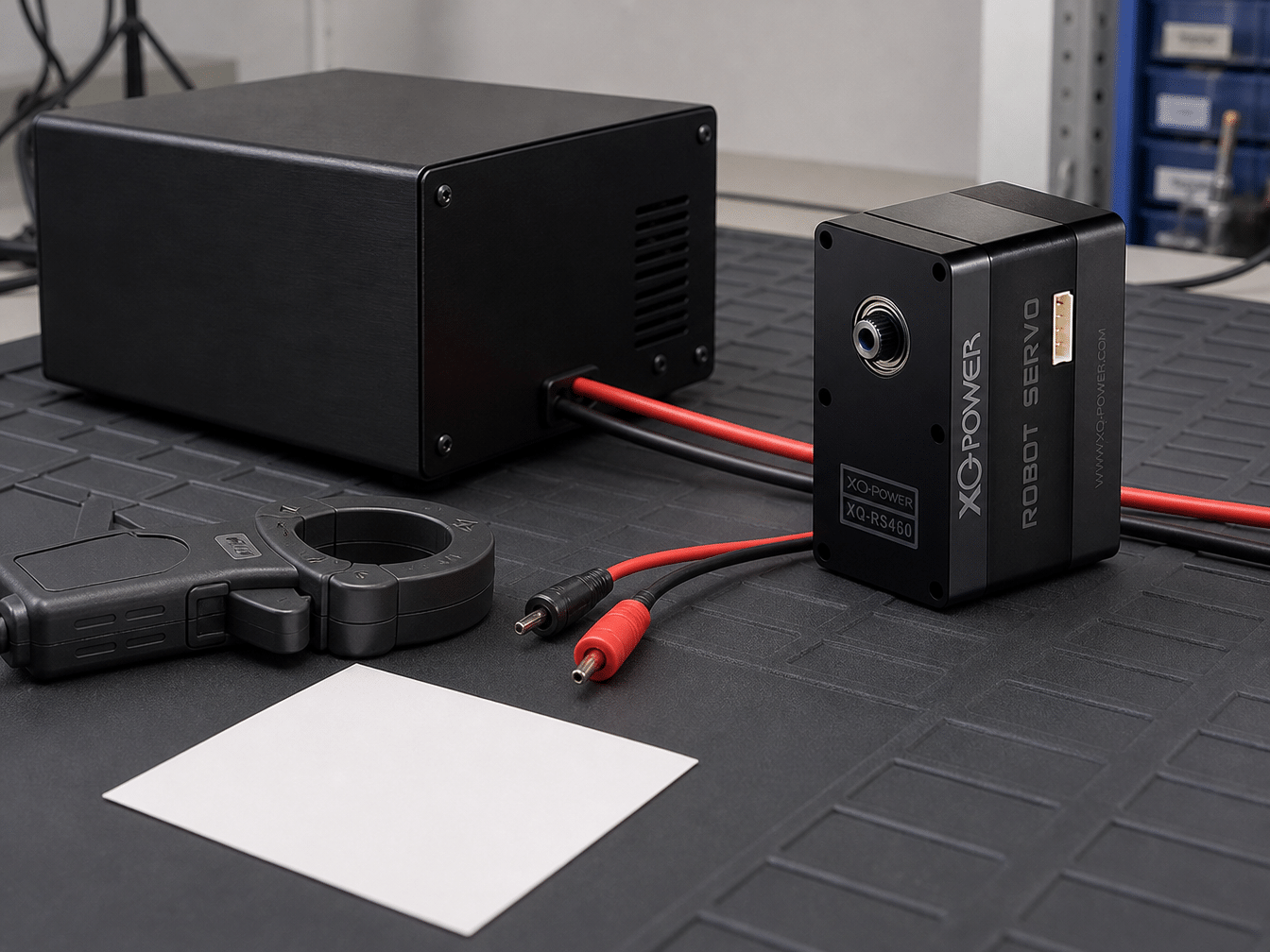
RS460 Modbus RS485 smart robot servo integrates a motor, smart servo drive, and Modbus interface. The page lists native 12 V input, 58 kg·cm torque at 12 V, position/temperature/speed/voltage/current feedback, and a CNC aluminum case with a toughened-steel gear train. It does not provide a numeric altitude limit, cold-start current curve, driver-board rating, or lubricant specification.
Can the driver board withstand a higher cold-start current?
It may, but the answer cannot be determined from stall current alone. Driver-board tolerance depends on power-switch ratings, safe operating area, current-sense range, current-limit thresholds, protection response time, PCB copper and thermal path, connector/cable/supply capability, firmware behavior, repeated-start duty cycle, cooling time, and minimum supply voltage.
The internal driver-board rating and protection thresholds are not published as one universal value for XQ-POWER servos. Do not infer them from a torque label or another model’s current data. A board may tolerate a short pulse but trip during a longer cold-start event; a limiter may protect the board but prevent breakaway torque. Both electrical survival and successful startup must be tested.
How does altitude affect a cold-start test?
Altitude is not simply a temperature label. Include ambient temperature and rate of change, air pressure and reduced air density, enclosure sealing, cooling behavior, battery chemistry and internal resistance, regulator performance, cable and connector condition, load changes, condensation, vibration, and shock.
The public product pages do not establish a universal altitude limit for the XQ-POWER range. Define pressure, temperature, electrical supply, vibration, and duty cycle together. A laboratory cold-chamber result may differ from a battery, long cable, sealed enclosure, and moving airframe.
How should the initial cold-start test be arranged?
- Select the exact model and variant; record voltage, interface, firmware, installation, and datasheet revision.
- Condition the complete assembly, including load, grease, cables, connectors, supply, and driver environment.
- Measure voltage at the servo terminals before the command and during the current peak.
- Apply the real startup load, including inertia, friction, leverage, coupling, and safe end stops.
- Capture current with sufficient bandwidth; record peak, duration, repetition, and current-limit behavior.
- Observe position and motion, including breakaway time, stalls, resets, noise, and final position.
- Check driver and case temperature; repeat at warm, target-low, and transition conditions.
What should be measured during a cold-start current test?
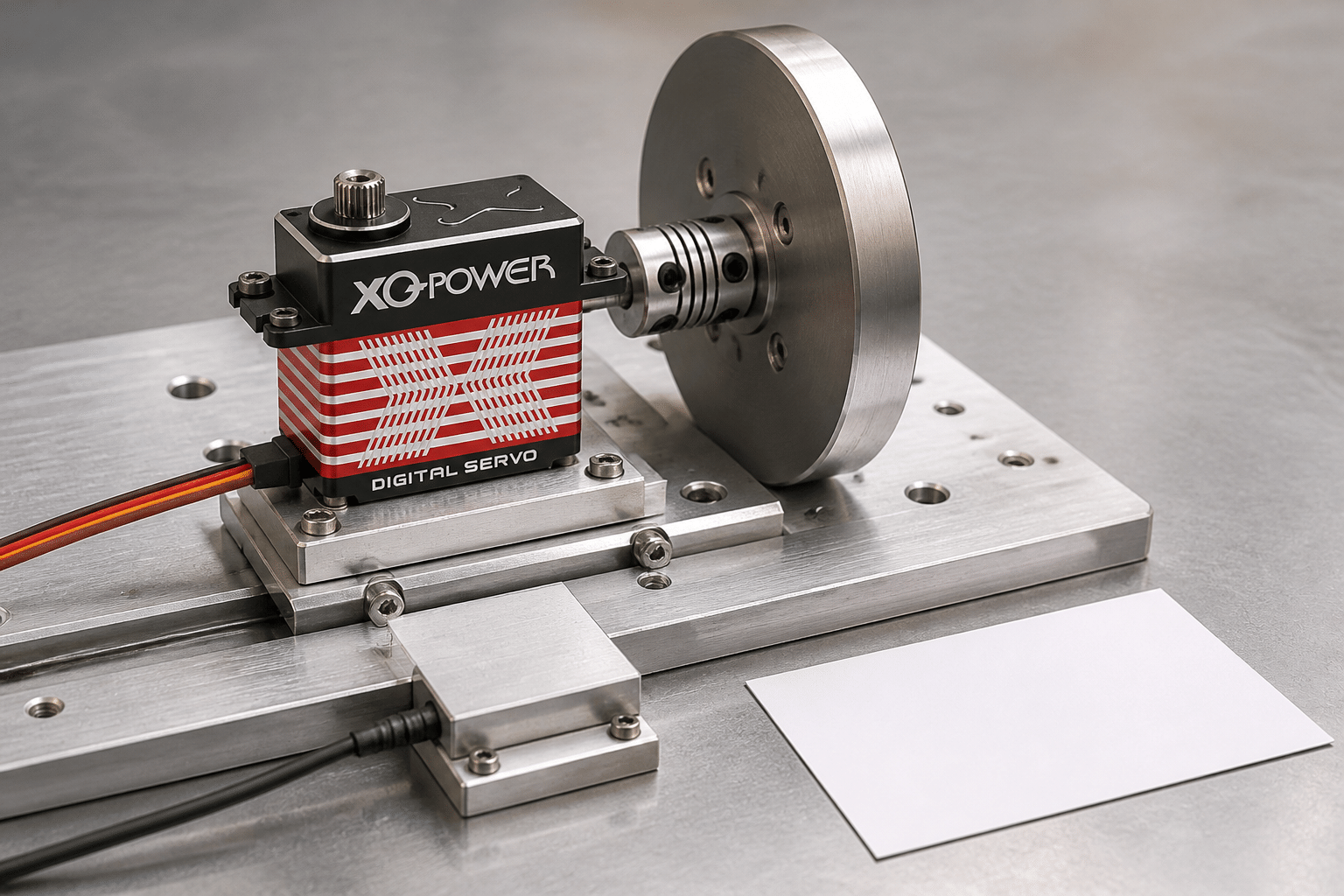
At minimum, record source voltage, voltage at the servo connector, startup current waveform, breakaway time, position response, driver-board temperature, case and gear temperature, start-stop count, fault/reset/current-limit events, ambient temperature, and pressure. A single maximum-current number is insufficient; store current-versus-time with voltage and position traces.
How should peak-current and repeated-start tests be performed?
Cold first-start test
After the complete assembly reaches the target low temperature, issue a defined command from rest and measure the first current peak, breakaway time, terminal voltage, and position response.
Repeated-start test
Command repeated starts and stops at the intended interval. Monitor current, movement, current limiting, and case warming; match the real rest period.
Reversal test
Reverse direction under the real load; direction changes can produce a different torque and current profile.
Near-limit load test
Use a controlled load representing the operating envelope. Do not intentionally exceed the specified limit merely to create a failure.
Warm-up and thermal recovery test
Continue the duty cycle after repeated cold starts to observe heating, then cool and repeat the sequence to check cycle-to-cycle behavior.
How can voltage drop create a false diagnosis?
A cold-start current peak may pull down supply voltage. Cable, connector, battery, or regulator impedance can leave the servo with less voltage when it needs the most torque, appearing to be a driver-board failure. Measure source voltage, distribution voltage, connector voltage, main-branch current, and individual-branch current where practical.
Check connector temperature and crimp quality. For multi-servo systems, use the multi-servo power and response guide and repeat with other axes active.
What does the XQ-POWER aging information tell engineers?
The XQ-POWER servo aging, vibration, and shock testing article describes continuous power-on aging, temperature cycling, long-duration start-stop cycling, and monitoring of current, positioning accuracy, return-to-center deviation, and jitter. This supports temperature cycling and repeated-start measurements but does not replace model-specific cold-start, altitude, or driver-board data.
What information should be requested for a high-altitude project?
- Exact operating and storage/transport temperature limits for the model and variant
- Altitude or pressure qualification, if available
- Cold-start current waveform and stall/peak-current test conditions
- Internal driver-board limits and protection behavior
- Recommended supply under cold battery conditions
- Lubricant guidance, cable and connector requirements
- Start-stop duty-cycle limits
- Vibration, shock, condensation, and environmental sample-testing support
If information is not in the datasheet, ask the XQ-POWER engineering team to define a test plan rather than extrapolating from another model.
How should the results be judged?
- The motor starts within the defined time.
- Terminal voltage remains inside the model’s specified range.
- Current peak and duration remain within the agreed electrical envelope.
- The driver does not reset, latch off, or enter an unexpected protection state.
- The servo reaches the required position under the specified load.
- Repeated starts do not cause progressive current increase or delayed movement.
- Driver, motor, gear, and case temperatures remain within approved limits.
Practical answer for UAV and high-altitude teams
- Select the exact XQ-POWER model and variant.
- Confirm published temperature and voltage information.
- Treat published stall current as a test-condition reference, not a cold-start specification.
- Measure current and voltage at the servo connector during a cold first start.
- Repeat under the real load and power source.
- Add repeated starts, reversals, and thermal recovery cycles.
- Include pressure/altitude, vibration, condensation, and battery conditions when relevant.
- Obtain engineering confirmation for driver-board margin and unstated values.
The question is not only whether the motor starts. The system must start reliably, hold position, protect the driver, and repeat the operation at intended environmental conditions.
Servo Cold-Start Current and High-Altitude FAQ
It can. Low temperature may increase lubricant viscosity, gear and bearing resistance, breakaway torque, and mechanism friction. The actual increase must be measured for the exact model, load, temperature, and supply.
No universal cold-start current value is published. No-load and stall-current points under specified voltage conditions are not automatically cold-start measurements. Request model-specific data or an engineering test.
That depends on driver design, current margin, protection threshold, response time, PCB thermal path, supply, and event duration. Confirm the exact model and test it under intended temperature and load.
No. Startup occurs during acceleration from rest, while stall current is measured with the output prevented from rotating under a defined condition. Measure waveform duration and mechanical condition.
No. Their listed temperature ranges do not establish an altitude limit, pressure qualification, cold-start curve, or airborne-system suitability. Test the complete application and confirm the exact variant.
Test cold first-start current, terminal voltage, breakaway time, loaded motion, repeated starts, reversals, temperatures, resets, current limiting, vibration, pressure/altitude, condensation, battery behavior, and the real load, cable, connector, controller, and duty cycle.
Need help evaluating a high-altitude servo application?
Send the exact model, target temperature, altitude or pressure, load torque, duty cycle, supply and battery conditions, cable layout, control interface, and required startup time to the XQ-POWER engineering team. The team can discuss model-specific data, sample testing, or an OEM/ODM environmental validation plan.