
An XQ-POWER servo housing may participate in a robot’s mechanical structure when the material, housing geometry, mounting ears, fasteners, mounting plate, load direction, and operating conditions have been evaluated. However, it should not be assumed that every servo housing can directly carry a large bending moment continuously.
The servo’s published torque rating describes the rotational output that the actuator is designed to produce under a defined test condition. It does not automatically define the external bending moment, radial load, or axial load that may be applied to the housing, mounting ears, output shaft, bearings, or fasteners.
For a robot leg joint, robotic arm, crawler mechanism, or other impact-loaded structure, a safer design approach is usually to let an independent bracket, shaft, pivot, or bearing carry the primary structural load while the servo supplies the drive torque. The exact allowable loading must be confirmed from the selected model’s structural parameters, installation requirements, and test results.
What is the difference between drive torque and bending moment?
Drive torque is the rotational output produced by the servo at its output interface. It turns a horn, spline, shaft, gear, linkage, wheel, or joint.
Bending moment is a rotational effect caused by a force acting at a distance from a support or axis. In a simple engineering approximation:
Bending moment = external force × perpendicular distance from the support
A robot foot, gripper, or arm can create a bending moment at the joint even when the actuator is only commanded to hold position. The moment may be transferred through the output shaft, bearings, housing, mounting ears, bolts, bracket, and frame.
These loads are related but not identical. A servo can have a high output-torque rating while the complete housing-and-mounting arrangement still requires a separate structural check for external loads.
Can the servo housing provide auxiliary structural support?
It can provide auxiliary support when the installation has been designed for the specific housing and load path. For example, the housing may be fastened to a stiff robot frame and help locate the actuator while the primary joint load is carried by a separate pivot or bearing.
Whether the housing can carry more than an auxiliary role depends on facts that vary by model and application:
- Housing material and wall thickness
- Housing geometry and unsupported span
- Mounting-ear shape and section thickness
- Bolt size, thread engagement, and fastener grade
- Mounting-plate material and stiffness
- Distance from the load to the mounting face
- Direction and magnitude of radial and axial loads
- Static load, cyclic load, vibration, and impact severity
- Output-shaft and bearing arrangement
- Temperature, corrosion, contamination, and service conditions
A housing may appear rigid during an unloaded bench check but deform when the mechanism applies a long-lever-arm load or repeated shock. The correct answer therefore requires a model-specific structural review and a test under the intended load cycle.
Why a separate bracket, shaft, or bearing is often safer
In a robot leg, the joint can experience body weight, ground reaction force, acceleration, landing shock, and side loads. In a robotic arm, the payload creates a changing moment as the arm extends. In a crawler or off-road mechanism, terrain and wheel contact can create sudden forces that are much higher than the smooth drive torque measured during normal motion.
An independent bracket, pivot shaft, or bearing can be designed to carry these structural loads. The servo can then drive the joint through a compatible output interface while the external support limits the load transferred into the housing and internal transmission.
This arrangement can reduce the risk of:
- Housing deformation
- Cracked or distorted mounting ears
- Loose or pulled fasteners
- Output-shaft misalignment
- Excessive radial or axial bearing load
- Gear wear caused by side loading
- Increased backlash and position error
- Vibration transmitted into the control loop
The exact architecture depends on the mechanism. A separate bearing is not a universal requirement, but it is an important design option when the joint carries a substantial external moment or impact load.
What does the XQ-POWER mounting guide recommend checking?
The XQ-POWER servo mounting guide states that mounting must be evaluated as a complete servo, coupling, linkage, and driven-load assembly. It identifies the mounting pattern, flange or pilot features, output spline or shaft, alignment, load direction, vibration, and mechanical clearance as relevant selection factors.
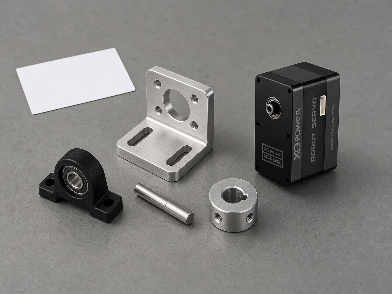
The guide also warns that cantilevered mounting can increase the bending moment applied to the mounting structure and fasteners. If the servo body or driven load extends away from the supported mounting face, the resulting leverage and vibration should be evaluated rather than assigned a generic unsupported-length limit.
During installation, check that:
- The mounting face is clean, flat, and adequately supported.
- The mounting plate is stiff enough for the reaction torque and external load.
- The servo output is aligned with the driven shaft or linkage.
- The output shaft is not exposed to unapproved radial or axial loading.
- The coupling, horn, hub, or spline has sufficient engagement.
- The complete mechanism has clearance through its full range.
- Fasteners have the required engagement and remain secure under vibration.
How do XQ-POWER product structures relate to this question?
XQ-POWER product pages publish construction details that help engineers begin a mechanical review, but these details do not by themselves establish an allowable housing bending load.
The S9150D 180 kg industrial brushless servo lists an all-metal CNC aluminum case, toughened steel gears, a 25T output with a 9.95 mm diameter, and a 2000-hour endurance test report link. These details are relevant when assessing the actuator’s envelope, output interface, and mounting concept. The page does not state a universal external bending-moment rating for the housing or mounting ears.
The RS460 Modbus RS485 smart robot servo lists a full CNC aluminum case, an 8 mm output shaft, dual industrial ball bearings, and a 58 kg·cm torque point at 12 V. It is presented for evaluation in multi-axis robotic and automation applications. These published features do not replace a structural calculation for an external robot-joint load.
The S9450D 700 kg·cm-class industrial servo lists an aluminum CNC case, eight ball bearings, and a 25T output specification. The S9750D 1000 kg·cm-class industrial servo lists an aluminum CNC case, ten ball bearings, and a 25T output specification. Their high output-torque classes do not automatically mean that the housings can serve as unsupported structural pivots under any external bending load.
Use the product data to define the mechanical interface, then request model-specific structural limits or testing when the housing is expected to carry a significant external moment.
What can happen when a housing carries an excessive bending moment?
If an external load exceeds the verified capacity of the housing or mounting arrangement, several failure modes are possible. The exact result depends on the load direction, duration, material, geometry, fasteners, and mechanism.
Housing deformation
A thin or unsupported section can deflect under load. Even a small deflection may alter the joint geometry, introduce backlash, or shift the relationship between the servo output and the driven link.
Mounting-ear damage
Mounting ears can experience local bending, bearing stress around the bolt hole, fatigue, or cracking. Repeated vibration and impact can be more damaging than a single smooth static load.
Fastener and frame failure
The bolts may loosen, pull out, shear, or deform the mounting plate. The frame itself may be less stiff than the actuator and become the main source of movement or misalignment.
Output-shaft and bearing side loading
A force applied away from the output axis can create radial or axial loading. This may increase friction, bearing stress, vibration, shaft deflection, or wear in the internal transmission.
Gear wear and position error
An external side load can change the alignment of the gear train and increase contact stress. Over time, the mechanism may develop backlash, noise, uneven motion, or position error even if the commanded output torque was not unusually high.
These risks are reasons to separate the drive path from the primary structural load path whenever the application has high bending moment, shock, or uncertain loading.
How should a robot joint be designed around the servo?
A robot joint should be designed as a complete load path rather than as a servo bolted to two moving links.
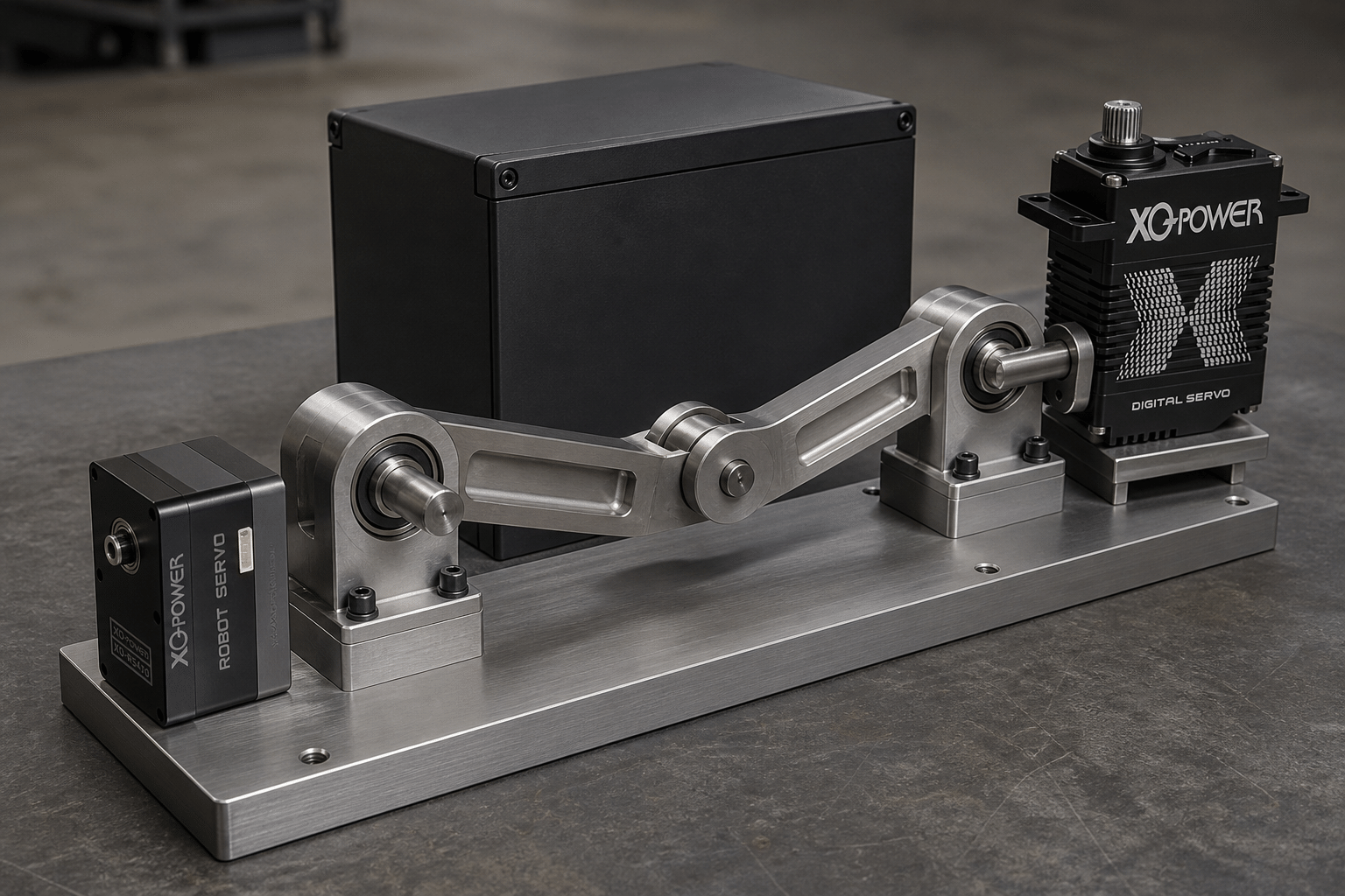
1. Define the external forces
Identify the payload, body weight, ground reaction, acceleration, gravity, friction, collision, and any expected impact. For a legged robot, include contact forces and landing events. For a robotic arm, include payload and the changing lever arm through the motion range.
2. Calculate the moment at the support
Estimate the external force and perpendicular distance from the bearing, pivot, mounting face, or support. Evaluate both the normal operating load and the transient peak load.
3. Choose the primary load path
Decide which bracket, pivot, shaft, bearing, frame, or linkage will carry the external force and moment. The servo should transmit the required drive torque through a compatible interface without becoming the only support for an unverified side load.
4. Check the servo interface
Confirm the exact output spline or shaft, engagement depth, horn or hub, mounting pattern, pilot, bolt pattern, clearances, and allowable loading in the model-specific documentation.
5. Validate stiffness and alignment
Check deflection under load, bearing alignment, linkage geometry, backlash, fastener preload, and clearance throughout the full range of movement. A structural deflection that is acceptable for a slow mechanism may be unacceptable for a precision robot joint.
6. Test static, cyclic, and impact conditions
Use guarded testing to apply the intended load and duty cycle. Record housing deflection, mounting-ear movement, output position, current, temperature, vibration, noise, fastener condition, and gear play.
How should static and dynamic bending loads be separated?
A static bending load is a relatively steady force or moment. A dynamic bending load changes with acceleration, reversal, vibration, contact, or shock. The dynamic case may be much more severe because inertia and structural resonance amplify the force.
For a robot leg or crawler, the joint may see a short impact when a foot or wheel contacts the ground. For a robotic arm, a sudden stop can create a transient load when the moving mass is decelerated. For both cases, the load path should be checked for:
- Peak force and moment
- Impact duration
- Repetition rate
- Reflected inertia
- Joint speed and acceleration
- Structural damping and stiffness
- Clearances and hard stops
- Fastener preload and fatigue
- Temperature and material changes
Do not infer impact capacity from a smooth stall-torque number. Stall torque measures output torque under a defined condition; it does not describe every external force applied to the housing, shaft, or bracket.
The stall torque versus continuous torque guide explains why a torque label must be interpreted with voltage, load profile, duty cycle, mounting, and thermal conditions.
How can a design reduce housing load?
The following design choices may help reduce the bending moment transferred into the servo housing, subject to the exact mechanism:
- Place a bearing or pivot close to the external load.
- Use a dual-support shaft when the joint geometry requires it.
- Keep the load line close to the supported bearing or mounting face.
- Use a rigid bracket with adequate section stiffness.
- Avoid cantilevering a heavy link from the output shaft alone.
- Use a compatible coupling or hub that does not introduce misalignment.
- Provide mechanical stops that do not impact the servo at operating speed.
- Distribute fastener loads through an appropriate mounting plate.
- Inspect the assembly after cyclic and impact testing.
These are design principles, not a substitute for the product-specific structural data or a qualified engineering review.
How should S9150D and RS460 be evaluated in robot structures?
The S9150D and RS460 illustrate two different integration scales.
The S9150D is a high-torque industrial brushless servo listed for robotic joints and AGV applications. Its product page provides the case, output, gear, voltage, torque, and endurance-test information. A robot designer may use these details to develop a mounting and output-interface concept, but the housing’s external bending capacity still needs to be confirmed for the intended joint.
The RS460 is a compact Modbus RS485 smart servo listed with a 58 kg·cm torque point at 12 V, an 8 mm output shaft, dual bearings, and telemetry fields. It may be evaluated in distributed robotic systems, but a compact package should not be assumed to carry a large structural moment simply because it offers integrated control and feedback.
In both cases, the structural bearing or pivot should be designed from the real load path, while the servo is selected for the required drive torque, speed, control interface, and duty cycle.
What information should be sent to XQ-POWER for a structural review?
If the housing is expected to form part of the robot structure, provide:
- Exact servo model and product variant
- Housing drawings or requested mounting dimensions
- External force and bending moment at the joint
- Radial and axial load components
- Load direction and lever arm
- Static, cyclic, and impact duty cycle
- Joint speed, acceleration, and range of motion
- Mounting-plate material and thickness
- Fastener type, number, spacing, and thread engagement
- Output spline, shaft, horn, or coupling design
- Operating temperature and environment
- Required deflection, backlash, and position-error limits
- Test method and acceptance criteria
This information allows XQ-POWER to determine whether a standard configuration is suitable, whether an independent support is required, or whether an OEM/ODM structural customization should be discussed.
For engineering selection or structural-load confirmation, use the XQ-POWER contact page.
Servo Housing and Robot Bending Load FAQ
It may provide auxiliary structural support when the material, housing geometry, mounting ears, fasteners, mounting plate, load direction, and operating conditions have been evaluated. However, no universal direct or continuous bending-load capacity should be assumed for every XQ-POWER model. The allowable load must be confirmed from model-specific structural data and testing.
No. Output torque is the rotational torque produced at the servo output interface. Housing bending capacity concerns external force and moment transferred through the mounting structure, housing, ears, fasteners, shaft, and bearings. They are related load-path questions but are not interchangeable ratings.
For a robot leg or other joint exposed to large bending moment, radial load, or impact, an independent bracket, pivot, shaft, or bearing is often a prudent design approach. It can carry the primary structural load while the servo supplies drive torque. The exact architecture depends on the joint geometry and must be validated for the real load cycle.
It should not be assumed without model-specific structural data and testing. A robotic-arm payload creates a changing moment as the arm extends, and acceleration or sudden stops can add dynamic load. Evaluate the complete housing, mounting, output interface, bearing, bracket, and frame rather than relying only on the servo’s torque rating.
Possible risks include housing deformation, mounting-ear damage, fastener loosening or pull-out, output-shaft misalignment, excessive bearing side load, gear wear, increased backlash, vibration, and position error. The actual failure mode depends on the model, geometry, material, fasteners, load direction, and duty cycle.
Provide the exact model, external force and moment, radial and axial loads, lever arm, load direction, static and dynamic duty cycle, mounting plate, fasteners, output interface, temperature, and required deflection or position limits. XQ-POWER can then review the application against model-specific drawings, structural data, and test requirements.
Need help designing a servo-supported robot joint?
Share the servo model, external force, bending moment, load direction, mounting design, output interface, duty cycle, and required deflection limits with the XQ-POWER engineering team. The team can help evaluate a standard servo, independent support structure, sample test, or OEM/ODM mechanical requirement.