
Direct answer: XQ-POWER servo gears do not automatically break whenever a robot experiences a high peak impact. However, a jump landing, collision, sudden stop, or hard contact can damage or fracture a gear when the instantaneous torque exceeds the mechanical load limit of the gear train. The correct engineering response is to compare the real peak torque, impact duration, impact count, reflected inertia, and mechanical compliance with the selected servo’s validated limits—not to judge shock resistance from a nominal torque number alone.
For dynamic robot joints, the actuator is only one part of the impact path. The foot, linkage, bearing, shaft, gear train, housing, frame, and ground-contact structure all influence how much energy reaches the gear teeth. A suitable XQ-POWER model, combined with adequate torque margin, elastic elements, damping, or a compliant joint design, can reduce the probability of tooth fracture and tooth-surface damage. The final design still requires joint-level testing with the actual mass, speed, motion profile, and collision condition.
At-a-Glance Shock-Load Takeaways
- A peak stall-torque rating is not the same as an allowable repeated impact rating.
- Gear tooth failure depends on torque magnitude, impact duration, contact position, tooth geometry, material, support stiffness, and repeated cycles.
- Robot jumps, landings, collisions, and abrupt reversals can produce loads far above a steady-state operating torque.
- A torque margin should be based on measured or calculated dynamic load, not only payload weight.
- Elastic feet, dampers, flexible couplings, current limits, and motion-profile control can reduce the impact transmitted to the gears.
- External bearing support and a rigid, aligned mounting structure help prevent unintended radial and bending loads on the output shaft.
- After impact testing, inspect tooth flanks, tooth roots, output bearings, shaft play, backlash, and position repeatability.
- XQ-POWER model selection should be confirmed against voltage, load inertia, duty cycle, gear structure, mechanical interface, and application-specific test data.
Why a Peak Impact Can Damage a Servo Gear Train
A gear tooth is loaded through a contact area that transfers torque from one gear to the next. Under normal motion, the load may be distributed across several teeth and remain within the expected operating range. During an impact, the joint can decelerate so quickly that the effective torque rises sharply.
The impact path can include several sources of amplification:
- Reflected inertia: A heavy link or wheel resists sudden changes in speed and reflects a larger load back to the output shaft.
- Short stopping time: The shorter the deceleration interval, the higher the instantaneous force required to stop the moving mass.
- Mechanical leverage: A contact force acting far from the joint axis creates a larger joint moment.
- Rigid contact: A hard landing or collision leaves little distance or time for energy absorption.
- Structural resonance: A flexible frame or linkage can store and release energy, creating a secondary peak.
- Backlash impact: Clearance between gear teeth can allow the teeth to strike when the direction reverses.
This is why a servo that operates reliably under a smooth test load may still suffer damage during a jump landing or collision. The damaging event is not necessarily the average torque; it is the short-duration maximum at the tooth contact.
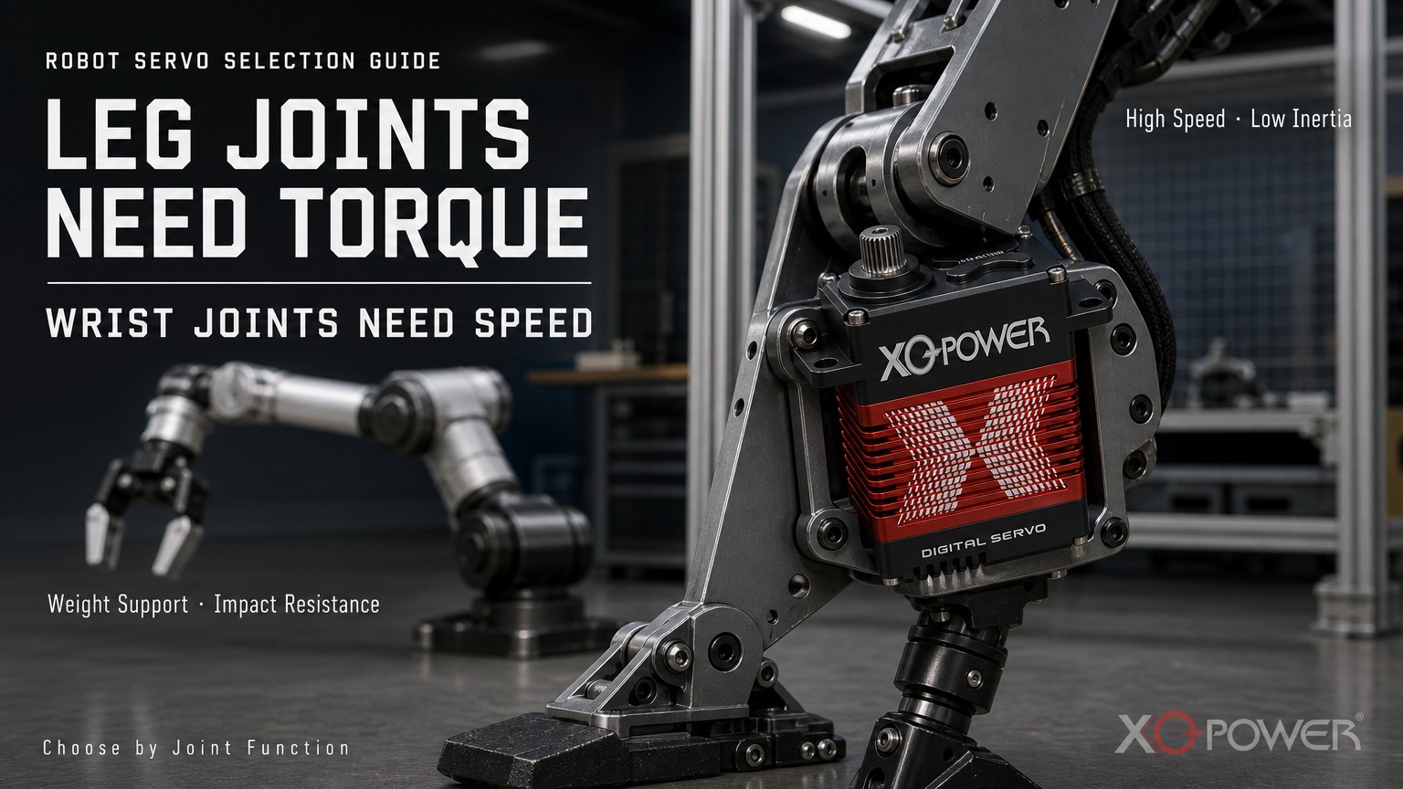
What Types of Gear Damage Can Occur?
“Gear failure” can describe several different damage modes. Identifying the mode helps engineers improve the mechanical design rather than simply installing a larger servo.
Tooth-root fracture
A tooth-root fracture occurs when bending stress at the base of the tooth exceeds the material and geometry limit. It can appear as a partially broken tooth, a complete tooth separation, or a crack that grows over repeated impacts.
Tooth-surface pitting or scoring
Repeated high contact stress can damage the working surface of a tooth. The joint may continue operating initially, but backlash, noise, vibration, and positioning error can increase over time.
Plastic deformation
A tooth may deform without immediately breaking. Deformation changes the contact pattern, concentrates load on neighboring teeth, and can accelerate later failure.
Gear-tooth chipping
A corner or edge can chip when the tooth engages under misalignment, excessive backlash, foreign material, or a sudden reverse load. The chipped area may create a periodic vibration as the gear rotates.
Output-shaft or bearing damage
Not every shock-related failure starts in the gear. A radial impact can load the output shaft and bearing, change alignment, or increase play. The resulting misalignment then raises tooth-edge loading and can cause secondary gear damage.
How Should Peak Torque Be Compared with Servo Ratings?
Peak torque, stall torque, holding torque, and continuous torque describe different operating conditions.
- Peak impact torque: The highest short-duration torque created by a landing, collision, sudden stop, or hard contact.
- Stall torque: Torque measured under a stalled or near-stalled test condition at a specified voltage and configuration.
- Holding torque: Torque required to maintain a static position against gravity or an external force.
- Continuous torque: Torque that can be sustained over the project duty cycle without exceeding validated thermal and mechanical limits.
- Repetitive impact torque: The peak load repeated over a defined number of events and intervals.
A gear train can survive one short event but fail after thousands of smaller impacts. The number of cycles, time between impacts, temperature, lubrication condition, and load direction all matter.
The XQ-S9750D product page gives a useful example of why voltage and test conditions must be stated. Its inspection specification records peak stall torque values of 850 kg·cm at 24 V, 920 kg·cm at 28 V, and 980 kg·cm at 30 V. These are product-specific peak stall results, not a universal allowance for robot collisions or repeated shock loading. The page also notes that final performance depends on voltage, load inertia, acceleration, duty cycle, mechanical leverage, thermal conditions, and the complete transmission design.
Review the XQ-S9750D 1000kg-class industrial servo as a product reference, then confirm the applicable impact and duty-cycle limits with XQ-POWER before finalizing a high-dynamic joint.
How Can Engineers Estimate a Robot-Joint Impact Load?
A first-order estimate begins with the kinetic energy of the moving mass:
E = 1/2 × m × v²
where m is the effective moving mass and v is its velocity at impact. The average stopping force can be approximated as:
F_average ≈ E / d
where d is the stopping distance. A shorter stopping distance produces a higher average force. The actual peak force may be higher because the deceleration is not perfectly uniform.
To convert the contact force into a joint moment:
T_impact ≈ F_impact × r
where r is the perpendicular distance from the joint axis to the impact force line.
These equations are engineering estimates, not substitutes for instrumented testing. For a robot leg or arm, use the effective mass and velocity at the contact point, include the linkage geometry, and evaluate the worst-case joint angle. If an elastic foot, damper, spring, tire, or flexible coupling changes the stopping distance, include that compliance in the model.
The robotic-arm servo selection and reliability guide provides related guidance on dynamic torque, gear loading, thermal behavior, encoder feedback, and multi-axis integration.
Which Mechanical Features Reduce Shock Transmission?
Elastic feet and compliant contact elements
An elastic foot or compliant contact pad can increase the stopping distance and spread the impact over a longer time. This can reduce the peak force transmitted to the joint, although it may introduce deflection, rebound, or control complexity.
Dampers and shock absorbers
A damper converts part of the impact energy into heat and limits the speed of the rebound. Select the damper for the actual mass, velocity, stroke, temperature, and cycle frequency. A damper that is too soft may allow excessive travel; one that is too stiff may transfer too much force into the gear train.
Flexible couplings or compliant joints
A controlled amount of torsional compliance can isolate a gear train from a sudden reversal. The coupling must still maintain alignment and avoid introducing uncontrolled oscillation or backlash.
Current and acceleration limiting
Controller settings can reduce the commanded acceleration, braking rate, and reversal aggressiveness. Current limiting can help prevent the actuator from producing an excessive corrective impulse, but it should not be treated as a replacement for mechanical protection.
External bearing support
When an output shaft is exposed to radial or bending loads, an external bearing can carry the structural load and let the servo focus on torque transmission. This reduces unintended loading of the output bearing and helps maintain gear alignment.
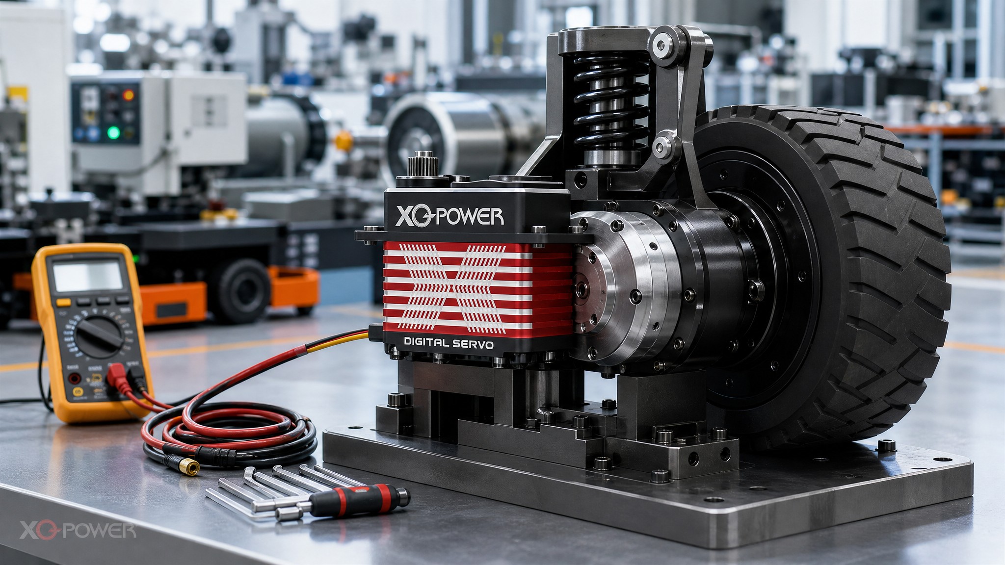
How Do Gear Material, Support, and Alignment Affect Impact Life?
Impact resistance is not determined by gear material alone. It also depends on tooth geometry, heat treatment, surface finish, reduction layout, lubrication, bearing support, housing stiffness, and alignment.
The XQ-POWER high-torque product range includes industrial brushless servo models with metal cases and steel gear structures. The S9750D product page identifies a CNC aluminum case, steel gear, and multiple ball bearings. Those features are relevant to high-load mechanical design, but the applicable external radial load, allowable bending moment, gear-life curve, and repeated-impact limit remain model- and application-specific values that should be confirmed with the engineering team.
Alignment is especially important during a shock. If the housing flexes or the output shaft is tilted relative to the driven linkage, the tooth load may concentrate at one edge instead of spreading across the intended contact area. Check:
- Mounting-face flatness;
- Shaft and linkage alignment;
- External bearing position;
- Fastener preload and retention;
- Housing stiffness;
- Tooth contact pattern;
- Backlash before and after impact testing.
For mechanical installation reference, consult XQ-POWER’s Technical Guide and confirm the selected model’s mounting and output-interface requirements.
What Should Be Tested in a High-Dynamic Robot Joint?
A no-load movement test cannot establish impact durability. Use a staged validation plan.
1. Baseline inspection
Record gear backlash, shaft play, bearing noise, no-load current, position repeatability, and housing condition before testing.
2. Static load test
Apply the expected holding load at representative joint angles. Confirm that the actuator maintains position without abnormal current, visible deflection, or unstable feedback.
3. Controlled dynamic test
Run the real acceleration, deceleration, reversal, and pause profile. Begin below the final target and increase the load gradually while recording current, position, temperature, and vibration.
4. Peak-impact test
Use an instrumented fixture or force/torque measurement where possible. Define the impact velocity, stopping distance, contact location, number of events, interval, and temperature condition. Do not rely on a single destructive event as the only acceptance test.
5. Repeated-cycle test
Repeat the impact or landing event for the expected mission count plus an engineering margin. Inspect for progressive backlash, gear noise, tooth-surface marks, position error, bearing play, and output-shaft looseness.
6. Post-test inspection
Disassemble only under a controlled procedure and inspect tooth roots, tooth flanks, gear edges, bearing races, shafts, fasteners, and housing interfaces. Compare the measured condition with the baseline record.
XQ-POWER positions its Solutions around industrial robotic arms, robot-dog platforms, humanoid robots, AGVs, and other demanding motion-control applications. The relevant impact test should still be designed around the customer’s actual robot geometry and mission profile.
How Does Encoder Feedback Help After an Impact?
Encoder feedback cannot prevent every mechanical fracture, but it can reveal changes that appear before complete failure. After a shock event, monitor:
- Position error at a known command;
- Settling time;
- Overshoot and oscillation;
- Repeated-position variance;
- Current required to hold position;
- Noise or vibration synchronized with gear rotation;
- Difference between commanded and externally measured output angle.
A sudden increase in backlash may appear as a larger dead zone around direction reversal. A damaged tooth may create a repeatable error or vibration at a particular output angle. A magnetic encoder can support closed-loop monitoring, but it cannot remove mechanical play between the encoder location and the final joint output.
How Should XQ-POWER Servo Models Be Selected for High-Dynamic Joints?
Start with the application rather than the product headline:
- Define the moving mass, joint axis, lever arm, speed, acceleration, and impact condition.
- Estimate static, dynamic, holding, and impact torque separately.
- Select the operating voltage and confirm the power supply’s peak current capability.
- Compare the model’s gear structure, output interface, bearing support, and housing envelope.
- Decide whether the project needs PWM, CAN Bus, RS485, MODBUS-RTU, or another confirmed interface.
- Add mechanical compliance or damping if the impact energy is not acceptable at the gear train.
- Validate the installed assembly before approving production.
For industrial robotic arms and high-inertia joints, XQ-POWER’s high-torque servo category can be used to review the available product range. The appropriate model still depends on the application-specific torque curve, voltage, inertia, duty cycle, mounting, and test requirements.
Frequently Asked Questions About Servo Gear Shock Loads
No. Gear failure is not inevitable. Damage risk rises when instantaneous torque, reflected inertia, impact frequency, misalignment, or tooth contact stress exceeds the mechanical limit of the selected gear train. Use adequate torque margin, mechanical compliance, and application-level validation.
No. Stall torque is a specified test result under a particular voltage and configuration. Shock-load capacity depends on impact duration, energy, contact geometry, number of events, temperature, gear support, and the complete mechanical structure.
It can reduce transmitted peak force by increasing stopping distance and absorbing part of the impact energy. The elastic element must be tuned to the robot mass, landing velocity, stroke, rebound behavior, and cycle frequency.
Inspect tooth flanks and roots, backlash, output-shaft play, bearing noise, housing fasteners, linkage alignment, current, position repeatability, and any vibration that occurs at a specific output angle.
No. Steel gearing can support demanding loads, but impact life also depends on tooth geometry, heat treatment, lubrication, bearings, housing stiffness, alignment, load direction, impact energy, and repetition count. Confirm the model-specific limits.
Yes. Provide the joint function, peak and continuous torque, speed, inertia, voltage, communication interface, mounting envelope, impact condition, duty cycle, and target service life. XQ-POWER can then review the suitable model or OEM/ODM path, subject to engineering validation.
Conclusion
XQ-POWER servo gears do not fail automatically under high-multiple peak shock loads, but no gear train should be treated as immune to impact. A robot jump, landing, collision, or hard reversal can generate a short-duration torque that is much higher than the normal working load. If that torque exceeds the gear system’s mechanical limit, tooth-root fracture, chipping, surface damage, backlash, or bearing failure may follow.
The most reliable approach combines a realistic impact-load estimate, sufficient peak torque margin, suitable gear and bearing support, accurate alignment, mechanical buffering, controlled acceleration, encoder-based monitoring, and repeated joint-level testing. For a product selection or custom project review, share the actual robot geometry and shock profile with the XQ-POWER engineering team rather than selecting by nominal torque alone.