
Direct answer: XQ-POWER digital servos can include stall/overload protection, while selected industrial and high-torque brushless models may also include overcurrent and overtemperature monitoring. The exact protection functions, trigger thresholds, response behavior, and recovery method depend on the servo model and configuration. Protection is a secondary safeguard—not permission to run the actuator continuously beyond its rated load, voltage, temperature, or duty cycle.
When a servo is blocked, stalled, or held under excessive load, the motor current can rise quickly. If that condition continues, the drive electronics, motor windings, gears, and printed circuit board may be exposed to excessive electrical and thermal stress. A protection system can detect part of that risk and limit output current, reduce available torque, enter a protective state, or require a power-cycle reset. Engineers should still select the servo from the complete load case and verify the actual protection behavior in testing.
XQ-POWER’s product portfolio covers standard digital servos, brushless high-torque servos, industrial actuators, magnetic-encoder systems, and solutions for robotics, AGVs, UAVs, and other demanding motion-control applications. This guide explains how to interpret servo protection features without treating a generic protection label as a substitute for model-specific documentation.
At-a-Glance Servo Protection Takeaways
- Stall or overload protection helps respond when the output is blocked or the actuator is forced beyond its normal operating condition.
- Overcurrent protection monitors excessive electrical demand and can limit or interrupt drive output.
- Overheat protection monitors thermal risk and may reduce output, enter a protective state, or require a reset.
- Basic brushed models and industrial brushless models may not share the same protection functions.
- Hardware monitoring and firmware logic can work together, but the exact implementation must be confirmed for the selected model.
- A protection event is a fault condition, not a normal operating mode.
- Repeated protection trips can indicate insufficient torque margin, excessive inertia, mechanical binding, poor alignment, or inadequate thermal design.
- After a trip, follow the model’s specified recovery procedure and investigate the cause before returning the system to service.
What Does Servo Overload Protection Do?
Servo overload protection is intended to reduce damage risk when the actuator experiences a load beyond its normal operating condition. Common triggers include:
- A jammed linkage;
- A stalled output shaft;
- A blocked wheel or gripper;
- A winch reaching the end of travel;
- A robotic joint pressing against a hard stop;
- A transmission that is misaligned or mechanically bound;
- A sudden external force that prevents the commanded movement.
During an overload event, a servo may limit current, reduce torque, stop driving, enter a fault state, or use another model-specific response. The objective is to prevent the motor, drive electronics, and gear train from being exposed indefinitely to a damaging condition.
The protection response does not guarantee that no component can be damaged. A short and severe mechanical impact may damage a gear before the electrical protection logic can react. A repeated overload may also cause cumulative heating even when every individual event appears brief. For this reason, overload protection should be treated as a backup layer within a broader mechanical and electrical safety design.
Is Overcurrent Protection Built into the Servo?
Selected XQ-POWER industrial and high-torque brushless servo configurations can include current monitoring and overcurrent protection. The function is designed to detect electrical demand that exceeds the applicable control or drive condition and then limit the risk to the motor and electronics.
Overcurrent protection can be useful when:
- The output is stalled;
- The load suddenly increases;
- The motor accelerates a high-inertia mechanism;
- A linkage binds during travel;
- The power system causes an abnormal current condition;
- A mechanical hard stop is reached;
- A wiring or controller fault creates unexpected electrical demand.
The protection threshold should not be guessed from the servo’s torque label. Current depends on voltage, motor state, load, acceleration, gear friction, control settings, and the electrical design of the selected model. A high-torque servo may naturally require more current during acceleration than a smaller servo, while the allowable current and protection response can vary by driver design.
When evaluating an XQ-POWER model, ask for the applicable current limits, stall-current behavior, protection threshold, fault response, reset method, and test conditions. The XQ-POWER Technical Guide is a useful starting point for reviewing servo sizing, communication, encoder, environmental, and thermal topics, but the product-specific specification remains the controlling reference.
Does the Servo Include Overheat Protection?
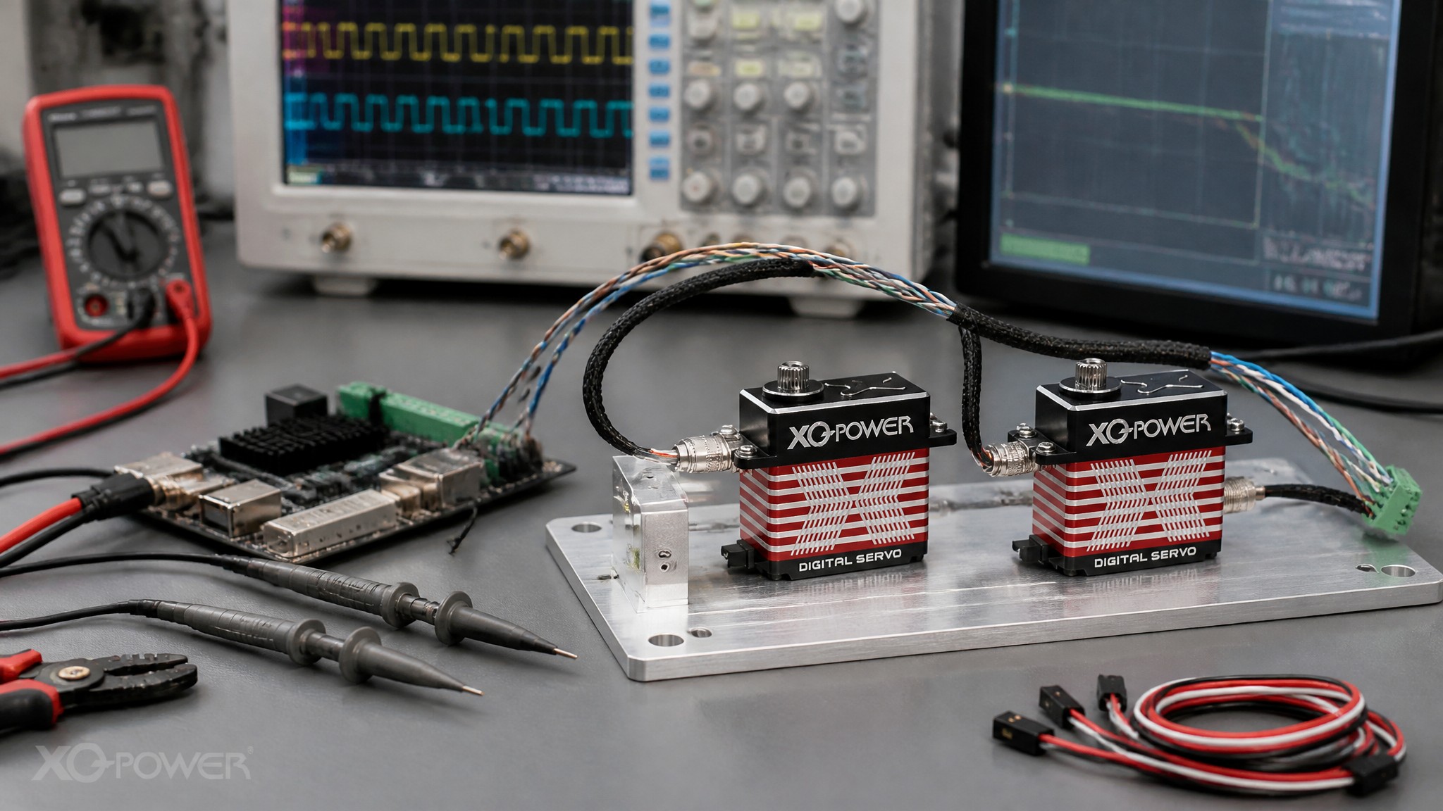
Selected high-performance brushless and industrial servo models can include temperature monitoring or overtemperature protection. This protection is intended to reduce the chance of damage when the actuator remains under high load, high current, or repeated operation for too long.
Heat can build up during:
- Continuous holding torque;
- Repeated acceleration and braking;
- High-frequency direction changes;
- Operation near stall;
- High ambient temperature;
- Restricted heat transfer from the housing;
- A sealed or enclosed installation;
- Excessive gearbox or bearing friction.
When the measured or estimated thermal condition exceeds the model’s protection limit, the servo may reduce output, stop driving, enter a protective state, or require a power reset. The exact behavior is model-specific. Do not assume that every servo uses the same sensor location, temperature model, threshold, hysteresis, or restart logic.
Thermal protection limits the damage risk; it does not make continuous overload acceptable. If a servo repeatedly reaches overtemperature protection, review the torque margin, duty cycle, voltage, motion profile, cooling path, mounting, and mechanical friction. A larger or differently configured actuator may be required.
How Do Hardware and Firmware Protection Work Together?
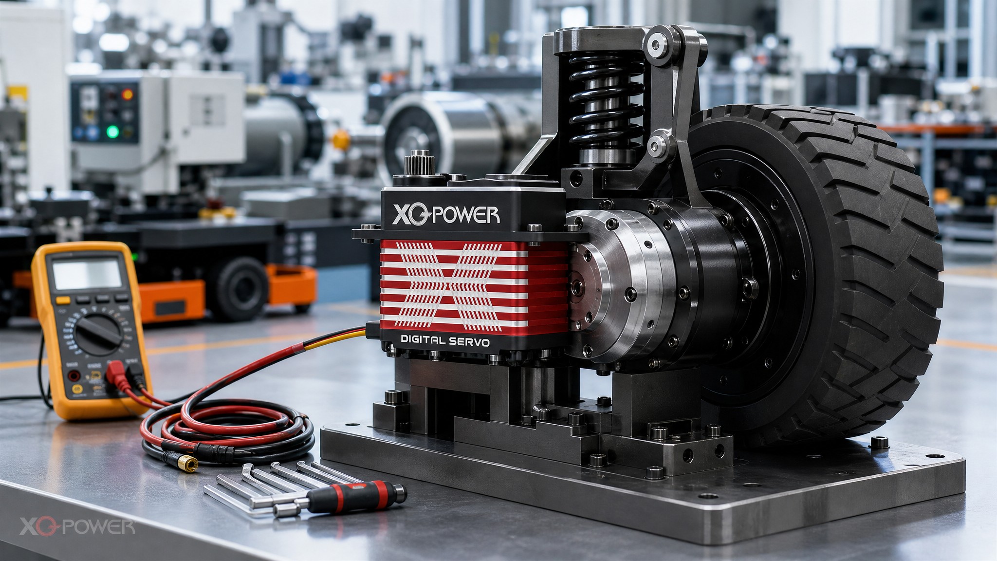
A modern digital servo can combine several layers of protection:
- Hardware current sensing: The drive circuit measures electrical demand and can react quickly to an abnormal current condition.
- Firmware monitoring: The controller interprets current, position, time, command state, and other signals to decide whether a protective response is needed.
- Thermal estimation or sensing: The system evaluates motor or driver temperature risk based on a sensor, a thermal model, or both.
- Mechanical limits: Gears, bearings, housing, shaft interfaces, and mounting structures provide the physical load boundary.
- System-level protection: The robot controller, power supply, fuse, current limiter, emergency stop, and motion planner add external safety layers.
These layers are complementary. Hardware may react quickly to an electrical fault, while firmware can apply timing, filtering, recovery, and diagnostic logic. Mechanical protection is still essential because electronic current limiting cannot prevent every shock, tooth fracture, bearing failure, or misalignment event.
The exact combination depends on the selected product. Before integration, request the protection description for the model variant rather than assuming that a function from one servo family applies to every XQ-POWER servo.
Do Brushed and Brushless Servos Have the Same Protection Functions?
Not necessarily. A basic brushed digital servo may provide stall or overload protection as its primary protective function, while overcurrent and overtemperature monitoring may be optional, configuration-dependent, or unavailable on that model. Industrial and high-torque brushless models may provide a more complete set of current and thermal monitoring functions, but this must be confirmed against the exact product specification.
The motor architecture affects the control electronics, current measurement, thermal behavior, and firmware capabilities. It does not by itself prove a particular protection feature. Selection should therefore compare:
- Motor type;
- Rated and operating voltage;
- Peak and continuous torque;
- Stall-current behavior;
- Driver and firmware functions;
- Temperature monitoring;
- Fault reporting;
- Reset behavior;
- Communication interface;
- Mechanical load and duty cycle.
The XQ-POWER brushless servo category contains multiple industrial and high-torque product families. Use the category to identify candidate models, then confirm the protection functions and limits for the exact model and communication variant.
What Happens When a Servo Protection Function Trips?
A protection event may produce one or more of the following behaviors:
- Reduced output current;
- Reduced available torque;
- Slower or restricted movement;
- Output shutdown;
- A fault or diagnostic indication;
- Temporary latch until the condition clears;
- Recovery after a power cycle;
- Recovery through a command or controller procedure.
Many servo systems can recover after power is removed and restored, but this is not universal. Some faults may remain active until the temperature falls, the mechanical obstruction is removed, a command sequence is sent, or the system is inspected. Never repeatedly power-cycle an actuator while the mechanical jam remains present.
A reset can restore operation without correcting the original cause. Before restarting, check the linkage, output shaft, gear train, wiring, supply voltage, controller command, end stops, and load condition. If the servo trips again, treat the repeated event as diagnostic evidence rather than as a normal feature of the application.
Can Protection Prevent Motor and Gear Damage in a Jammed Mechanism?
Protection can reduce electrical and thermal stress, but it cannot guarantee that a jam will not damage the mechanism. The outcome depends on how quickly the fault develops, how much torque is produced before the protection responds, the duration of the event, the mechanical stiffness, the gear structure, and the number of repeated events.
For a jam-prone mechanism such as an RC vehicle steering system, robotic arm, or winch, combine servo protection with:
- Adequate torque margin;
- Mechanical travel limits;
- Slip clutches or compliant couplings where appropriate;
- External bearing support;
- Current-limited power distribution;
- Controller acceleration and force limits;
- A reliable emergency stop;
- A defined recovery procedure;
- Inspection after abnormal loading.
For higher-load applications, XQ-POWER’s high-torque servo category can help identify suitable industrial candidates. Final selection still requires the actual payload, lever arm, speed, inertia, voltage, duty cycle, and mechanical interface.
How Should Protection Be Tested?
Protection should be tested in a controlled fixture, not first discovered in a customer’s machine.
Stall and blocked-output test
Apply a controlled obstruction or torque load while monitoring supply current, output behavior, temperature, fault state, and recovery. Keep the test duration within an approved safety plan and use appropriate mechanical shielding.
Overcurrent response test
Increase the load or commanded acceleration in controlled steps. Record the current level at which the servo limits output or enters a protection state. Do not infer a universal threshold from one sample or one voltage.
Thermal endurance test
Run the real motion profile with the intended load, mounting, enclosure, and ambient condition. Record housing temperature, motor current, duty cycle, cycle count, position error, and any protective response.
Restart and recovery test
After a protection event, follow the specified recovery procedure. Check whether the servo recovers automatically, requires a power cycle, requires a command, or remains latched until the fault condition clears.
Repeated fault test
A single trip does not reveal how the system behaves after repeated faults. Define the number of events, time between events, starting temperature, and post-test inspection criteria. Check gears, bearings, wiring, output play, noise, position repeatability, and housing condition.
The XQ-POWER Solutions page covers applications including industrial robotic arms, heavy-duty AGVs, robot dogs, humanoid robots, and other motion-control systems. Each application requires its own protection and recovery validation because the fault energy and consequences differ.
How Do Engineers Select a Servo with the Right Protection Level?
Use the following sequence:
- Define the failure modes: stall, jam, collision, excessive current, high temperature, communication loss, and power interruption.
- Calculate the normal, peak, holding, and continuous load conditions.
- Select the operating voltage and verify the power supply’s current capacity and protection.
- Identify whether the candidate servo provides stall, overload, overcurrent, and overtemperature protection.
- Confirm the protection trigger conditions, response, fault reporting, and reset method.
- Check the motor type, gear train, output bearing, mounting, and thermal path.
- Test the complete servo and mechanism under the real duty cycle.
- Document the recovery procedure for operators and service personnel.
For a product inquiry, provide the application type, expected load, speed, voltage, motion frequency, stall risk, ambient condition, communication protocol, mounting dimensions, and desired protection behavior. XQ-POWER states that its product experts can review application requirements and recommend a suitable drive module or customized solution.
Frequently Asked Questions About XQ-POWER Servo Protection
XQ-POWER digital servos can include stall or overload protection, but the exact function depends on the model. Industrial and high-torque brushless configurations may provide additional current and thermal monitoring. Confirm the selected model’s protection description before production use.
Selected industrial and high-torque brushless models can include overcurrent monitoring and protection. The applicable threshold and response are model-specific and should be confirmed from the product documentation or engineering team.
Selected high-performance models can include temperature monitoring or overtemperature protection. The trigger condition, output response, hysteresis, and recovery method vary by model and configuration.
The servo may limit current, reduce torque, slow or stop output, enter a protective state, or require a reset. Remove the mechanical cause and follow the model-specific recovery procedure before restarting.
No. Protection is an auxiliary safeguard, not a continuous-duty operating mode. Repeated overload or protection trips indicate that the load, inertia, thermal design, mechanical alignment, or servo selection needs to be reviewed.
Protection is especially useful in mechanisms that can jam or become overloaded, including RC vehicles, robotic arms, AGV mechanisms, winches, grippers, valves, and other automated equipment. The protection system should still be validated with the actual mechanism.
Conclusion
XQ-POWER servo protection can include stall or overload protection, while selected industrial and high-torque brushless models may add overcurrent and overtemperature monitoring. These functions can limit current, reduce output, or place the actuator into a protective state when a jam, excessive load, or thermal condition is detected.
The correct engineering approach is not to rely on protection as a substitute for sizing. Calculate the load, provide torque margin, design the mechanical stop and thermal path, choose the appropriate motor and communication variant, and test the protection response under controlled conditions. Confirm the exact functions, thresholds, recovery logic, and optional configurations with XQ-POWER before releasing the system for production.