
A heavy actuator is only as useful as the control network that can command it reliably. In a large UAV, vehicle mechanism, or robotic joint, the controller must coordinate motion, read feedback, recover from faults, and fit inside a carefully managed power and mechanical envelope.
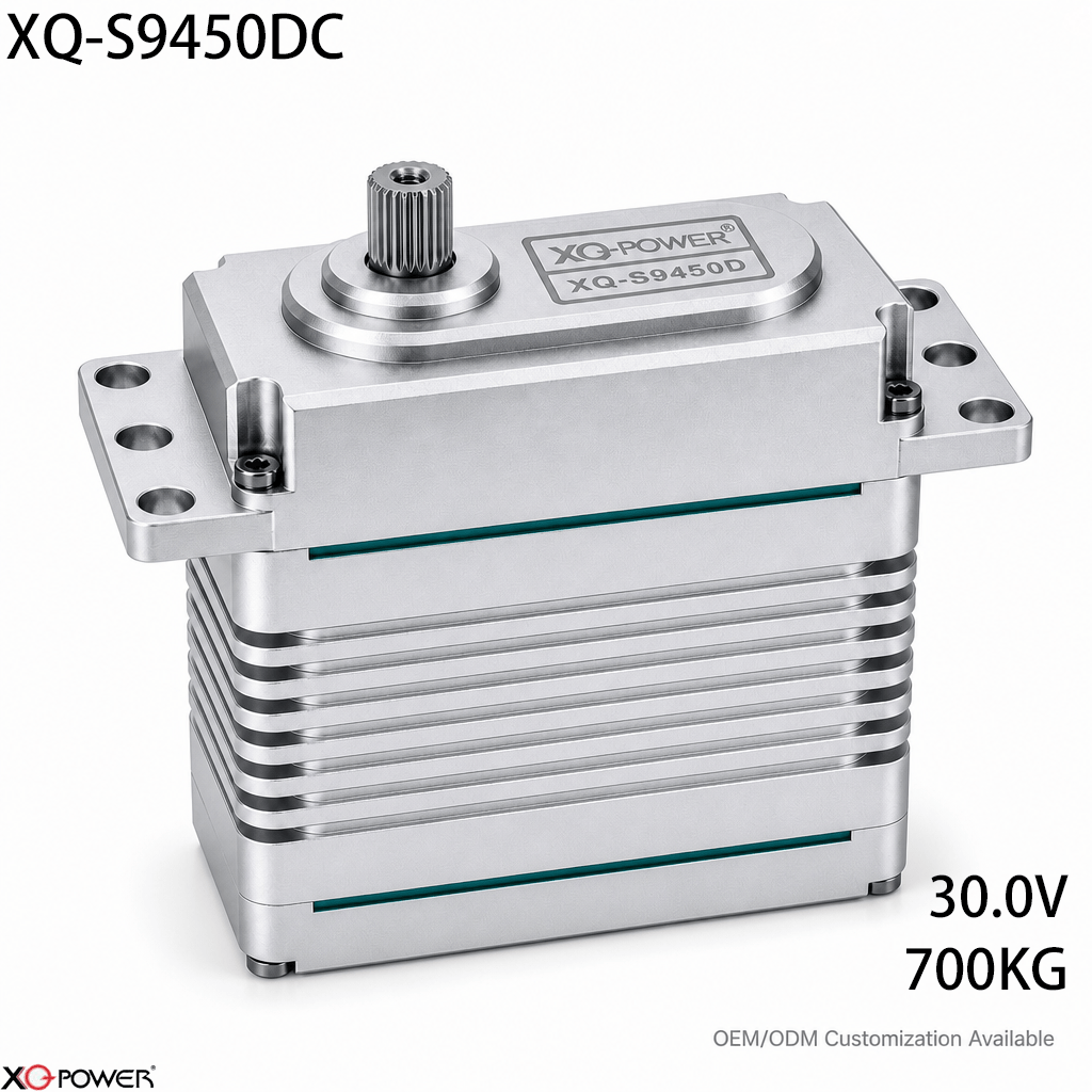
The XQ-S9450DC is a CAN Bus industrial brushless actuator positioned for heavy-lift UAVs and automotive robotics. The product page specifies 700kg torque, 0.21 sec/60° at 30V, a 24–30V operating range, CAN Bus communication with UAVCAN support, a magnetic encoder, a CNC-machined aluminum case, toughened steel gears, eight ball bearings, and a 25T, φ11.98mm output shaft.
This guide is not a second product-page summary. It addresses the engineering decisions behind a CAN-based heavy-motion axis: when CAN is a better fit than RS485 or PWM, how to evaluate Pixhawk integration, and how to test a high-inertia joint before flight or production use.
Begin with the flight-control or vehicle architecture
The first selection question is not “How much torque does the actuator have?” It is “Where will the actuator sit in the complete control architecture?”
For a UAV or robotic vehicle, map the following before selecting the final actuator:
- the flight controller or vehicle controller;
- the CAN interface and supported protocol;
- the number of CAN nodes on the network;
- the feedback required by the control loop;
- the available supply voltage and current capacity;
- the mechanical role of the actuator, such as a control surface, steering mechanism, landing system, or robotic joint;
- the behavior required after a communication interruption or controller restart.
The S9450DC product page identifies CAN Bus and UAVCAN support and references advanced flight controllers such as Pixhawk. The exact firmware, message definitions, node configuration, and commissioning steps should be confirmed against the target controller and the applicable actuator documentation.
Decide when CAN is a better fit than PWM or RS485
CAN, RS485, and PWM solve different system problems. A useful comparison starts with the machine’s wiring and feedback requirements rather than with a general protocol ranking.
CAN is a strong candidate when:
- the system needs a shared bus for multiple motion nodes;
- the controller already supports CAN or UAVCAN;
- the design benefits from bus-level error handling;
- motion feedback must be exchanged through the same network;
- the actuator is part of a coordinated UAV or vehicle subsystem.
RS485 may be a better fit when:
- the machine is already built around serial industrial control;
- the system uses a PLC or industrial controller with an RS485 architecture;
- the design depends on a documented register-based communication model;
- the installation is a factory motion cell rather than a flight-control network.
PWM may remain simpler when:
- only a small number of actuators are required;
- the controller already provides conventional servo pulses;
- the system does not need network addressing or telemetry;
- the shortest commissioning path is more important than distributed feedback.
The best choice is the protocol that matches the controller, node count, diagnostics, and software team. For a CAN-enabled flight-control system, the S9450DC is relevant because it combines high-load actuation with a network-oriented interface.
Use the 30V point as a power-system constraint
The product page gives a 24–30V voltage range and identifies 30V as the reference point for 700kg.cm torque and 0.21 sec/60° speed. This should be treated as a complete power-distribution decision.
For a heavy UAV or robotic vehicle, verify:
- whether the battery or DC bus can maintain the required voltage during rapid load changes;
- whether the regulator or power-distribution system can support the actuator’s demand;
- whether cable losses are acceptable at the actuator location;
- whether several actuators can move simultaneously without destabilizing the supply;
- whether the controller’s startup and restart behavior is defined;
- whether the mechanical system has an independent limit strategy for unexpected commands.
A nominal bus voltage is not the same as a validated operating condition. The final test should measure voltage at the actuator while the real joint, control surface, or vehicle mechanism is moving.
Evaluate CAN and UAVCAN integration before flight testing
The product page identifies UAVCAN support and compatibility with advanced flight-control systems such as Pixhawk. That is useful starting information, but a flight-ready integration requires more than a connector and a protocol label.
Before flight testing, confirm:
- Node identity — Every actuator must have a known identity and commissioning record.
- Message configuration — Confirm the command, position, status, and feedback messages used by the target controller.
- Update behavior — Check that command and feedback timing matches the control-loop requirement.
- Fault handling — Define how the controller responds to a missing node, invalid data, restart, or bus interruption.
- Parameter storage — Record travel limits, direction, startup behavior, and any application-specific settings.
- Bench reproduction — Test the exact firmware, wiring, controller, power system, and actuator configuration before installing it on the aircraft or vehicle.
This process turns “CAN-compatible” into a documented system configuration that another engineer can reproduce.
Match the mechanics to high-inertia motion
The S9450DC is specified with a 25T, φ11.98mm output shaft, toughened steel gears, eight ball bearings, and a CNC-machined aluminum case. These features should be reviewed together with the driven mechanism.
For a high-load UAV surface, steering system, or robotic joint, inspect:
- horn or adapter compatibility with the 25T output interface;
- bracket stiffness under peak torque;
- linkage alignment and side loading;
- backlash or compliance in the complete mechanism;
- actuator mass and its effect on balance or moving-link inertia;
- access to the connector and mounting fasteners;
- the load path from the actuator case into the airframe or vehicle structure.
A powerful actuator cannot correct a flexible bracket, poorly aligned linkage, or unsuitable load path. The actuator and the structure must be validated as one motion assembly.
Use magnetic feedback as part of the control review
The product page identifies an integrated magnetic encoder. In a CAN-based motion system, the value of feedback is determined by how the controller uses it.
Feedback can support:
- position confirmation after a command;
- detection of unexpected mechanical resistance;
- actuator commissioning and direction checks;
- maintenance records for repeated motion cycles;
- fault investigation after a sudden stop;
- synchronization of multiple motion nodes.
Before implementation, confirm the encoder data format, resolution, update behavior, and controller-side interpretation. Do not design a safety function around an unspecified feedback field; obtain the relevant technical documentation first.
Test the actuator in the final control loop
A bench test that only confirms rotation is not enough for a 700kg-class actuator. The validation plan should reproduce the electrical, mechanical, and network conditions of the final system.
Test 1: CAN node discovery and configuration
Verify node identity, controller recognition, command direction, feedback response, and parameter persistence without the full mechanical load.
Test 2: Static mechanical loading
Install the actuator on the representative bracket and check holding behavior, structural movement, output alignment, and load transfer at defined positions.
Test 3: Dynamic motion profile
Reproduce the expected acceleration, deceleration, travel, command rate, and duty cycle. Record supply voltage, feedback values, temperature, and controller status.
Test 4: Network disturbance and recovery
Test controller restart, power interruption, node removal, and communication recovery. Define the expected actuator state for each event before the system is used in the field.
Test 5: Integrated vehicle or UAV subsystem test
Run the complete control surface, steering mechanism, landing system, or robotic joint with the final controller and power system. Use recorded data to confirm that the actuator remains within the intended operating envelope.
Frequently Asked Questions
The product page identifies UAVCAN support and references advanced flight controllers such as Pixhawk. Compatibility should be confirmed against the exact controller firmware, UAVCAN message configuration, node settings, power architecture, and actuator documentation before flight testing.
CAN can be a strong fit when the aircraft needs a shared motion bus, distributed nodes, feedback exchange, and bus-level error handling. RS485 may be more appropriate for a PLC-centered industrial network. The correct choice depends on the flight controller, protocol implementation, node count, and system diagnostics.
It may be considered when the arm requires the specified torque class and can accommodate the 24–30V supply, CAN interface, actuator mass, output shaft, mounting structure, and duty cycle. A prototype should reproduce the real payload and acceleration profile.
Check the controller and power-distribution ratings, voltage at the actuator under load, wiring and connector capacity, simultaneous-node demand, startup behavior, and the manufacturer’s technical documentation. Validate the complete system rather than applying voltage to the actuator in isolation.
No. Suitability also depends on surface loads, linkage geometry, actuator speed, mounting stiffness, power availability, controller compatibility, feedback behavior, and the required duty cycle. Flight-control testing should reproduce the real mechanical and electrical conditions.
Provide the torque and speed profile, controller model, CAN or UAVCAN requirements, number of nodes, voltage, cable arrangement, mechanical interface, duty cycle, target quantity, and validation criteria. This allows the actuator to be evaluated against the actual UAV or robotic subsystem.
Selection summary
The XQ-S9450DC should be evaluated as a 700kg-class CAN Bus motion node for heavy-lift UAVs, automotive robotics, and other distributed high-load systems. Its published 30V operating point, 0.21 sec/60° speed, 24–30V range, UAVCAN support, magnetic encoder, CNC-machined aluminum case, toughened steel gears, eight ball bearings, and 25T, φ11.98mm output shaft define a system-integration task—not just a torque purchase.
The practical next step is an application-specific bench and subsystem test using the target flight controller or vehicle controller, final CAN configuration, power distribution, mounting structure, mechanical load, and fault-recovery sequence.