
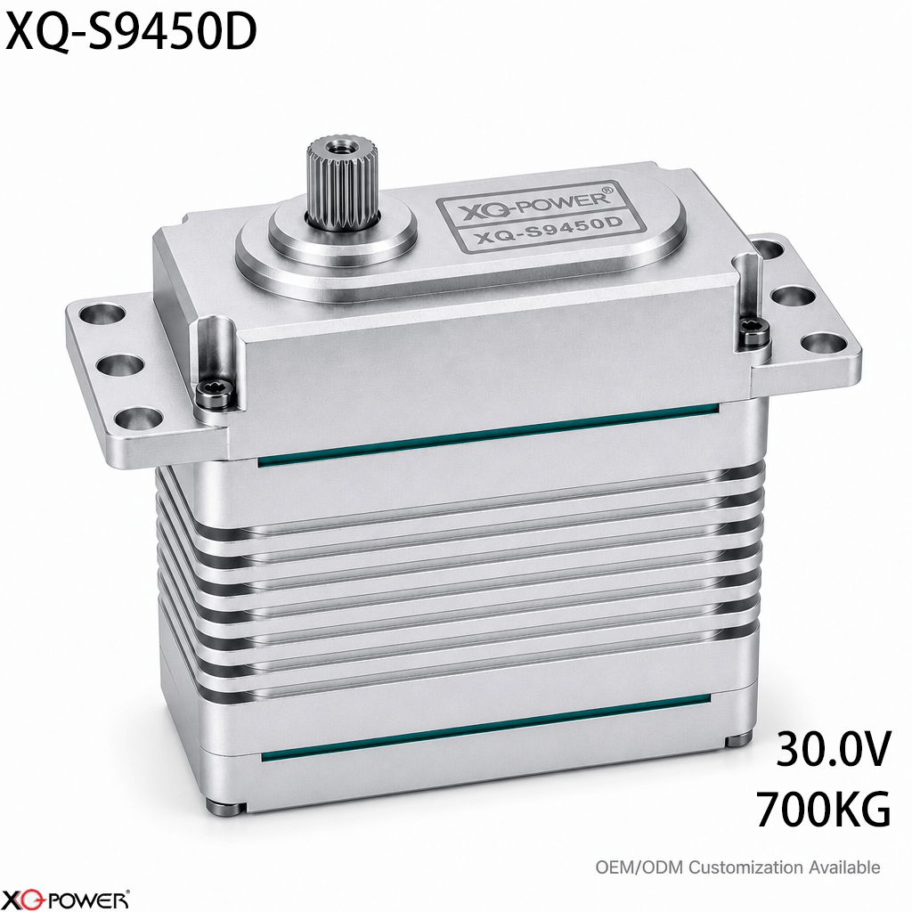
When a motion axis must move a large inertial load, servo selection should begin with the mechanical task—not with a generic torque number. The XQ-S9450D is a 30V industrial brushless servo rated at 700kg.cm (9,721oz-in) at 30V, with a published operating speed of 0.21 sec/60°. Its combination of high output torque, multi-protocol control, a CNC-machined aluminum case, a toughened steel gear train, and eight industrial ball bearings makes it a candidate for heavy robotic joints and large-scale automation where actuator structure and control integration must be evaluated together.
This article takes a different approach from a conventional product description: it explains how an engineer can decide whether the S9450D fits an axis, what information to verify before integration, and which questions matter when the load is heavy, dynamic, or difficult to service.
Start with the motion axis, not the servo catalogue
A 700kg.cm actuator is not automatically the correct choice for every heavy mechanism. The useful question is whether the actuator’s output interface, speed, voltage range, mounting envelope, and control method match the actual axis.
Before requesting a sample, document these five items:
- Peak and continuous torque demand — Separate the torque needed to accelerate the load from the torque needed to hold or move it continuously.
- Required angular travel and speed — The published S9450D reference point is 0.21 sec/60° at 30V. Confirm whether this response is suitable for the mechanism’s duty cycle.
- Available electrical power — The product page identifies a 24–30V operating range and a 30V performance point. The power supply, wiring, fuse strategy, and controller should be specified as a complete system.
- Control architecture — The S9450D supports PWM, S-Bus, CAN, and RS485/485 according to the product information. Select the interface that matches the existing controller and diagnostic requirements.
- Mechanical envelope — The supplied specification image identifies a 100.0 × 50.0 × 97.0mm body and a weight of 895g ±0.2. Check clearances, mounting stiffness, cable access, and the effect of actuator mass on the joint balance.
This checklist helps separate a genuine high-load requirement from a simple preference for the largest available servo.
Use the 30V operating point as a system-design decision
The S9450D is presented as a 30V high-voltage industrial servo. That matters because the actuator, power distribution, controller, and protection components must be selected as one electrical system. A 30V design should not be treated as a drop-in replacement for a low-voltage RC servo installation.
For a new machine, define the bus voltage first, then confirm:
- whether the controller supports the selected signal or bus protocol;
- whether the supply can handle the actuator’s current demand during acceleration and load changes;
- whether cable length and connector selection suit the installation;
- whether the control software can set travel limits, startup behavior, and fault handling;
- whether the mechanical stop strategy prevents the output shaft from being forced beyond its intended travel.
The product page lists a peak current figure of 22.5A for the S9450D platform. The final power design should still be based on the application’s measured current profile and the manufacturer’s technical documentation, rather than on a single marketing figure.
Match the communication method to the machine
The S9450D supports PWM, S-Bus, CAN, and RS485/485 interfaces. These options serve different integration patterns.
- PWM is useful when the motion controller already provides conventional servo pulses and the system is relatively simple.
- S-Bus can be considered when a compatible multi-channel control architecture is already in place.
- CAN is relevant to distributed motion systems that need a shared bus and coordinated nodes.
- RS485/485 can suit installations built around serial communication and industrial controller integration.
The important selection question is not “which protocol is newest?” It is: Which interface gives the system the clearest command path, the most useful feedback, and the least redesign of the existing control cabinet? Before mass production, confirm the exact command map, address behavior, telemetry fields, termination requirements, and commissioning procedure with XQ-POWER.
Why the mechanical stack matters at 700kg.cm
At this torque level, the actuator should be evaluated as a mechanical stack rather than as a motor alone. The product information identifies a toughened steel gear train, eight industrial ball bearings, and a 25T, φ11.98mm output shaft. These details affect how the actuator transfers load into the horn, bracket, linkage, or robotic joint.
During design review, check the following interfaces:
- Is the horn or adapter compatible with the 25T output spline?
- Can the mounting plate resist torsion without flexing?
- Is the linkage aligned closely enough to avoid side-loading the output shaft?
- Can the joint absorb shock loads without transferring them directly into the gear train?
- Is the actuator’s 895g mass included in the moving-link inertia calculation?
These questions are especially relevant to heavy robotic arms, large positioning mechanisms, and other systems where a small amount of structural compliance can become visible as oscillation or positioning error.
Brushless architecture: evaluate the whole duty cycle
The S9450D uses an industrial brushless motor. For engineers comparing brushless and coreless servo architectures, the meaningful comparison is the complete duty cycle: peak torque, holding time, acceleration profile, thermal environment, feedback behavior, and service interval.
A brushless motor can be attractive for a demanding industrial axis, but motor type alone does not prove suitability. Ask for the operating envelope and test method behind the published ratings. For a production project, evaluate sample units under the same supply voltage, load profile, mounting arrangement, and command rate that the final machine will use.
A practical selection path for robotics and automation teams
Use this four-stage process before approving the S9450D for a build:
1. Confirm the load case
Calculate the torque required at the output shaft for acceleration, gravity, friction, and external disturbance. Record both peak and continuous values instead of selecting from a single static load estimate.
2. Confirm the 30V electrical architecture
Check the power supply, current capacity, cable routing, connector system, emergency stop behavior, and controller compatibility. The chosen voltage must be supported by every part of the motion chain.
3. Confirm the mechanical interface
Validate the 100.0 × 50.0 × 97.0mm envelope, 895g mass, mounting pattern, output spline, and linkage geometry in CAD before ordering production quantities.
4. Run application-representative tests
Test the actual joint, not only the actuator on a bench. Measure startup response, current, temperature, repeatability, vibration, and behavior during rapid load changes. Record the controller settings so the result can be reproduced.
Frequently Asked Questions
Its published 700kg.cm torque at 30V and industrial mechanical construction make it a candidate for high-load motion systems. Final suitability depends on the joint’s acceleration torque, duty cycle, mounting stiffness, output interface, and controller compatibility.
Confirm the controller’s supported interface—PWM, S-Bus, CAN, or RS485/485—together with the command format, voltage range, feedback options, wiring, and commissioning procedure. Obtain the applicable communication documentation before building a multi-node system.
Yes. The 25T, φ11.98mm output specification should be matched with a compatible horn or mechanical adapter. The mounting bracket and linkage should also be checked for alignment and side-load behavior.
The S9450D is documented as a 24–30V industrial servo with a 30V torque rating. A model-aircraft installation should only be considered after verifying the aircraft’s power system, actuator mass, required speed, control interface, and mechanical load. Do not assume compatibility with a typical low-voltage receiver system.
It may be considered when the arm requires a high-torque actuator and the designer can accommodate the actuator’s dimensions, 895g mass, 30V electrical architecture, output spline, and control interface. A prototype test should reproduce the arm’s real acceleration and payload conditions.
Provide the target torque profile, speed, voltage, control protocol, output interface, installation envelope, duty cycle, quantity, and test criteria. This gives the engineering team enough information to assess the actuator against the real motion axis rather than against a generic specification.
Final selection summary
The XQ-S9450D should be evaluated as a complete high-inertia motion module: 700kg.cm at 30V, 0.21 sec/60° at the published 30V point, PWM/S-Bus/CAN/RS485 control options, a 100.0 × 50.0 × 97.0mm envelope, 895g mass, a toughened steel gear train, eight industrial ball bearings, and a 25T, φ11.98mm output shaft. For heavy robotics and automation, the best next step is an application-specific sample test using the final power system, controller, mounting structure, and load profile.