
Servo Motor Mounting Options: Flange, Spline and Shaft Guide
Servo motor mounting options determine how the actuator transfers torque and reaction loads into the machine structure. The correct choice depends on the mounting pattern, flange or pilot features, output spline or shaft type, coupling, alignment, load direction, vibration, and available mechanical clearance.
Before selecting a mounting method, confirm the exact servo dimensions, bolt pattern, pilot diameter, output interface, allowable loading, and installation conditions in the applicable product specification. A mounting solution should be evaluated as part of the complete servo, coupling, linkage, and driven-load assembly.
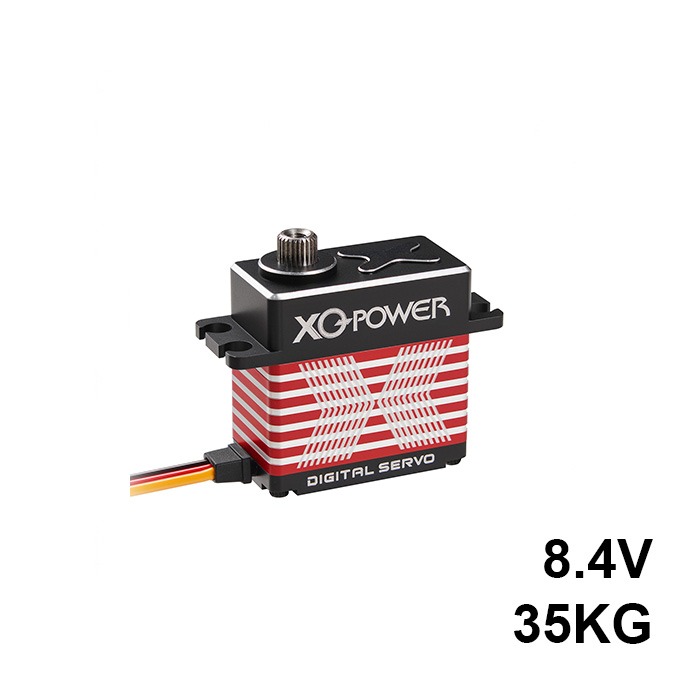
Face-Mount and Flange-Mount Options
A face-mount servo is secured to a plate or bracket through a defined bolt pattern. The mounting plate must be stiff enough to resist torque reaction, vibration, and the loads transferred through the driven mechanism. The correct bolt size, thread engagement, plate material, and fastening method depend on the servo specification and the machine structure.
A flange or pilot feature can help locate the servo body relative to the mounting plate and driven mechanism. It may also help maintain alignment, but it does not replace correct structural design or fastening. Confirm the pilot diameter, fit, mounting face, allowable tolerance, and installation direction from the exact product datasheet.
Do not select a mounting plate thickness or bolt pattern from a general rule. The required structure depends on torque, load direction, lever arm, vibration, acceleration, material, fastener arrangement, and the stiffness of the complete assembly.
Spline, Shaft, and Coupling Interfaces
The output interface is the connection between the servo and the driven mechanism. Common interfaces may include spline outputs, round shafts, D-shafts, keyed shafts, clamping hubs, or dedicated servo horns. The available interface depends on the exact model and variant.
A spline connection must be matched by tooth count, geometry, engagement depth, material, and compatible horn or hub. A shaft-and-hub connection must also account for clamping, keying, alignment, radial loading, axial loading, and the possibility of backlash or slip during operation.
Do not assume that two servo models with a similar appearance share the same output interface. Verify the spline specification, shaft diameter, flat or keyway details, output attachment, and allowable loading before ordering or machining a mating component.
Alignment and Mechanical Clearance
Misalignment between the servo output and the driven shaft can increase friction, radial loading, bearing stress, and vibration. Check the mounting face, pilot or locating feature, coupling, linkage, and driven shaft as one mechanical system.
During installation, verify:
- The mounting face is clean, flat, and adequately supported.
- The servo output is aligned with the driven component.
- The coupling or linkage allows the required movement without binding.
- The output shaft is not exposed to unapproved radial or axial loading.
- The servo arm, horn, hub, or coupling has sufficient engagement.
- The complete mechanism has clearance through its full range of motion.
A servo should not be judged by static fit alone. Check the assembly under the actual direction of load, acceleration, speed, and duty cycle.
Cantilevered Mounting and Structural Support
Cantilevered mounting can increase the bending moment applied to the mounting structure and fasteners. If the servo body, bracket, or driven load extends away from the supported mounting face, evaluate the resulting leverage and vibration.
A rear support, secondary bracket, or stiffer mounting structure may be appropriate in some installations. The correct solution depends on the servo dimensions, load direction, distance from the mounting face, operating vibration, and structural material. Do not apply a fixed unsupported-length limit without an engineering calculation or product-specific installation requirement.
Selecting the Right Mounting Method
Use the following sequence when selecting a servo mounting arrangement:
- Define the load torque, reaction torque, acceleration, speed, and duty cycle.
- Confirm the servo dimensions, mounting pattern, flange or pilot features, and output interface.
- Check the coupling, horn, hub, linkage, and driven-shaft compatibility.
- Evaluate radial and axial loading, alignment, clearance, vibration, and structural stiffness.
- Confirm voltage, controller compatibility, feedback, communication interface, and environmental conditions.
- Review the complete assembly under the expected operating conditions before production use.
A strong servo cannot compensate for an unsuitable bracket, misaligned coupling, unsupported load, or incompatible output interface.
Related Servo Selection Resources
For high-torque model comparison, visit the High Torque Servo category. For protocol, sizing, and integration guidance, visit the Technical Guide. For application-specific product selection or OEM/ODM support, contact the XQ-POWER engineering team.
Frequently Asked Questions
The main options depend on the product design and may include face mounting, flange or pilot mounting, servo-horn connections, spline outputs, round shafts, D-shafts, keyed shafts, clamping hubs, and dedicated couplings. Confirm the available interface and dimensions from the exact product specification.
Compare the required torque, load direction, duty cycle, allowable backlash, alignment, maintenance requirements, and compatibility with the driven hub or coupling. The final choice must match the servo’s documented output interface and the complete mechanical design.
Misalignment can increase friction, radial or axial loading, bearing stress, backlash, and vibration. Check the mounting face, pilot feature, coupling, linkage, output attachment, and driven shaft as one assembly before applying the operating load.
Provide the servo model, required torque, voltage, speed, duty cycle, mounting dimensions, output spline or shaft requirements, coupling or linkage design, load direction, operating environment, and any observed vibration or alignment issue. The XQ-POWER engineering team can then review the application and discuss product selection or OEM/ODM support.
For model-specific mounting dimensions, output-interface confirmation, or application engineering support, contact XQ-POWER.