
Servo Motor Sizing Guide: Stop Guessing, Start Calculating
A servo motor sizing guide isn’t something you need when everything works. It’s something you desperately wish you’d read after the third motor burns out on a production line. I’ve seen it happen: an integrator picks a servo based on “this one worked on the last project,” installs it on a heavier load, and six weeks later the winding insulation fails because the motor was running at 140% of its rated continuous torque eight hours a day.
Sizing an industrial servo motor comes down to three numbers: peak torque, continuous torque, and load inertia ratio. Get any one of them wrong and the system either fails early or costs twice as much as it should.
Peak torque is what the servo needs to accelerate the load from standstill. The formula is straightforward: T_peak = (J_load + J_motor) x angular acceleration + T_friction + T_gravity. The angular acceleration term is where most mistakes happen. If your mechanism needs to reach full speed in 200ms instead of 500ms, the torque demand jumps by 2.5x. That’s not linear — it’s the difference between a 50kg-cm servo and a 130kg-cm servo.
Continuous torque is what the servo sees during steady-state operation. For an AGV steering application, this is the torque required to hold a wheel angle against road friction and return-to-center forces. For a robotic joint, it’s the torque to hold position against gravity plus any process force. The rule of thumb: your servo’s rated continuous torque should be at least 30% above your calculated steady-state load. Below that margin, thermal buildup in the motor windings will degrade insulation life. A servo running at 85% of rated torque continuously might last two years. The same servo at 55% rated torque could last ten.
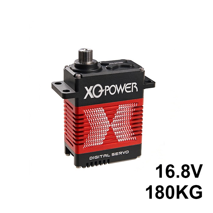
Load inertia ratio is the trickiest one because it depends on the mechanical transmission. Direct-drive applications demand that the motor rotor inertia be close to the load inertia — ideally a ratio below 3:1. Geared or belt-driven systems can tolerate higher ratios, typically up to 10:1, because the reduction ratio squares the reflected inertia. For example, a 5:1 gearbox reduces the reflected load inertia by a factor of 25. This is why an S9750-class heavy-duty servo with a 1000kg load rating uses internal gear reduction: without it, the motor rotor would need to be impractically large to match the load inertia of a loaded AGV.
Duty cycle ties it all together. A servo that accelerates for 1 second, runs steady for 10 seconds, and cools for 30 seconds has an RMS torque well below its peak. The same servo running 1 second on, 2 seconds off needs much more headroom. Calculate RMS torque as the square root of the time-weighted average of torque squared over one complete cycle.
The bottom line: pick up a torque wrench before you pick up a purchase order. Measure or calculate your actual load, not the optimistic estimate. Then size your servo motor with at least 1.3x headroom on continuous torque and verify the inertia ratio against your transmission type. Your production uptime will thank you.
[Internal links: Engineering Capabilities Hub, S9750 Product Page, Heavy Duty AGV Steering Article]