
Mechanical engineering for UAV and autonomous platforms is not simply a matter of selecting a motor with enough force. The actuator, airframe, payload, control surfaces, power architecture, communication network, and mechanical load path must work as one system. A reliable design begins by defining how the platform will move, what loads it will experience, how the actuator will be mounted, and how feedback will be used during operation.
For UAVs, this may include flight-control surfaces, payload mechanisms, gimbals, landing systems, or attitude-related actuation. For autonomous ground or robotic platforms, the same engineering logic applies to steering, articulated joints, tool mechanisms, and distributed motion systems. XQ-POWER’s product portfolio and solutions pages cover motion-control applications ranging from UAV systems and robotics to industrial automation, with servo options that include brushless designs, magnetic encoder systems, CAN Bus, and RS485 communication.
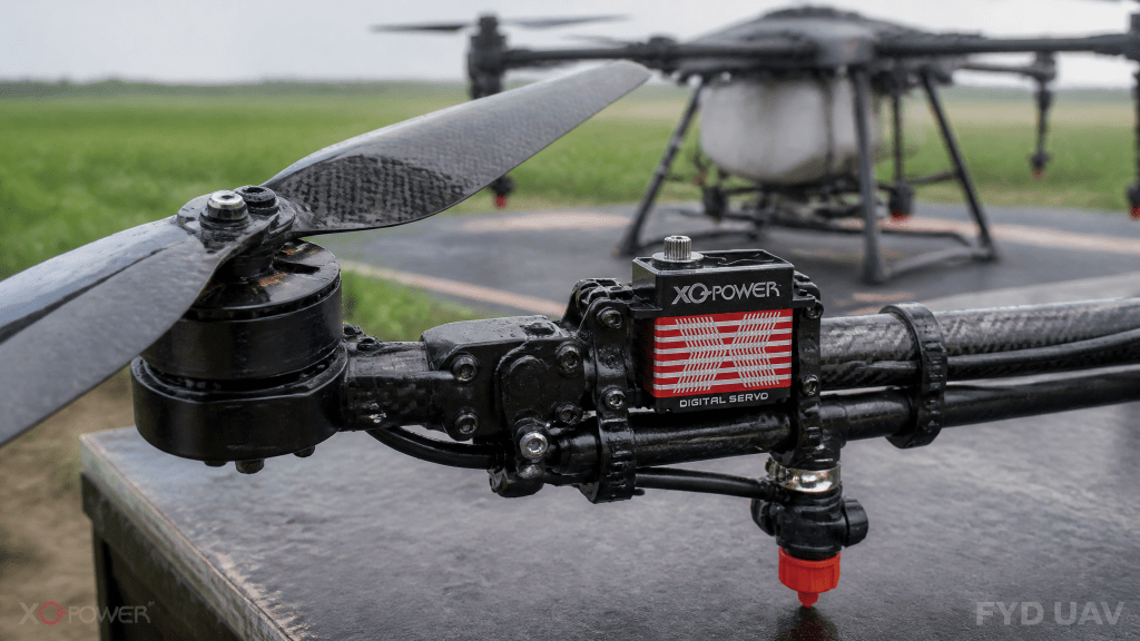
At-a-Glance Engineering Takeaways
- Design the UAV or autonomous-platform load path before selecting an actuator.
- Match servo torque, speed, voltage, inertia, mounting dimensions, and output interface to the mechanism.
- Treat servo installation, airframe structure, bearing support, alignment, and clearance as one mechanical assembly.
- Manage vibration, shock, thermal changes, backlash, and fastener retention during the design stage.
- Integrate feedback, communication, power distribution, and service access into the mechanical packaging.
- Define OEM/ODM requirements and system interfaces before requesting a customized actuator solution.
- Validate the complete platform under representative acceleration, vibration, payload, temperature, and duty-cycle conditions.
UAV Structural Design: Build the Airframe Around the Load Path
UAV structural design begins with the forces that the airframe must carry and the way those forces reach the frame. Flight-control surfaces, payload mounts, landing mechanisms, gimbals, and propulsion-related actuators each create different reaction loads. The structure must transfer those loads without excessive flexure, local deformation, or fastener movement.
Start by mapping the actuator output to the driven component. Identify the servo bracket, horn or shaft, linkage, hinge, pivot, bearing, and airframe attachment points. Then define the load direction at each interface. A bracket that appears rigid under a static hand check may still deflect when the platform accelerates or when the payload moves away from the center of gravity.
For autonomous ground and robotic platforms, use the same method for steering assemblies, articulated joints, tool heads, and distributed actuator frames. Keep high-load paths short where possible, support the reaction torque with the airframe or joint housing, and avoid using thin panels or unsupported covers as primary structural members unless their stiffness has been validated.
Servo Installation and Structural Integration
Servo installation is a structural integration task, not only a fastening step. The servo body, mounting plate, fasteners, output interface, linkage, and driven load must form a stable assembly. The actuator should not be expected to absorb loads that belong on a bearing, pivot, or dedicated support.
During integration, check the mounting face, bolt pattern, pilot or locating feature, fastener engagement, bracket stiffness, output support, and service access. The installation should maintain alignment when the mechanism is loaded, not only when it is unloaded on a workbench.
Document the installation requirements in the mechanical drawing. Include the actuator envelope, hole pattern, output interface, cable exit, allowable load direction, and removal path. This prevents a late-stage packaging change from forcing a new linkage or weakening the airframe structure.
Payload and Inertia Matching
Payload matching requires more than multiplying mass by gravity. The design team should calculate the moment created by the payload center of gravity, then consider the reflected inertia seen by the actuator through the linkage or transmission. A payload positioned farther from the pivot can require more holding torque and can also increase acceleration and deceleration loads.
Evaluate both static and dynamic conditions:
- Payload mass and center-of-gravity offset;
- Link or bracket mass carried by the joint;
- Required acceleration and deceleration;
- Transmission ratio and efficiency;
- Friction, imbalance, and mechanical compliance;
- The worst joint or gimbal position;
- Required holding time and repeatability.
An actuator may have enough static torque but still respond poorly if the reflected inertia is too high for the control system. Check settling behavior, overshoot, vibration, and current demand during the actual movement profile. Final inertia limits and control-loop compatibility require model-specific engineering validation.
Vibration and Shock Management
UAVs and autonomous platforms experience vibration from propulsion, rotating assemblies, road or terrain input, gear trains, and structural resonance. Shock loads can occur during landing, collision avoidance, abrupt direction changes, payload release, or a vehicle striking an obstacle.
Vibration and shock management should cover the complete chain from the moving load to the actuator case. Use a stiff mounting structure, avoid unsupported cantilevered brackets, retain fasteners against loosening, and ensure the output linkage cannot strike a hard stop unexpectedly. Check whether the mechanism has a natural frequency near a dominant excitation source.
During validation, inspect:
- Bracket deflection and fastener movement;
- Output-horn or shaft retention;
- Linkage backlash and joint wear;
- Bearing support and alignment;
- Connector retention and cable strain relief;
- Position error during repeated shock events.
Do not treat a servo with a high torque label as automatically shock-proof. The airframe, mounting hardware, linkage, and load profile determine the actual shock environment.
Thermal Changes and Their Effect on the Structure
Thermal changes can affect more than the actuator’s electronics. Temperature variation can change bracket dimensions, preload, bearing fit, lubricant behavior, cable flexibility, and the relative alignment between the servo output and the driven mechanism. A structure that is aligned at one temperature may develop clearance or preload changes at another.
Review the materials and interfaces around the actuator. Consider different thermal expansion coefficients between the servo case, mounting plate, fasteners, bearing carrier, and linkage. Check whether a constrained bracket can transfer thermal stress into the servo body or output bearing.
High duty cycles can also raise actuator and local structure temperatures. Measure temperature at representative load and operating conditions, then check whether position error, backlash, mounting movement, or linkage friction changes during the test. The exact permissible temperature range and thermal limits must be confirmed from the applicable model documentation.
Mechanical Clearance and Alignment
Mechanical clearance and alignment determine whether the actuator can deliver predictable motion. Insufficient clearance can cause binding at one point in the travel range. Excessive clearance can create backlash, impact loading, or inconsistent positioning. Misalignment can add radial or axial loads that were not included in the original torque calculation.
Check the complete mechanism through its full travel, including the worst payload position and the expected structure deflection. Confirm that the servo output, horn, coupling, shaft, linkage, hinge, and driven component remain aligned under load.
A practical inspection sequence is:
- Verify the mounting face is flat, clean, and adequately supported.
- Confirm the output interface is concentric or correctly oriented to the driven part.
- Move the mechanism slowly through its full range without power.
- Check for tight spots, hard stops, side loading, and cable interference.
- Repeat the check under representative load and after thermal cycling.
Use the exact model dimensions and output-interface information before machining mating parts.
Actuator-to-Airframe Mounting Methods
The actuator can be attached to an airframe or autonomous-platform structure through a face mount, flange or pilot feature, side bracket, saddle mount, or a dedicated joint housing, depending on the model and mechanism. The correct method is determined by load direction, reaction torque, available space, vibration, service access, and the need to support external bearings.
A face or flange mount is appropriate only when the plate can carry the reaction load and maintain alignment. A side bracket may be useful where packaging is constrained, but it must be checked for bending and torsional deflection. A joint housing can provide better support when the actuator drives a bearing-supported shaft, but the housing dimensions and output coupling must match the selected model.
Before finalizing the installation, verify:
- Actuator body dimensions and mounting pattern;
- Fastener size, engagement, and access;
- Pilot, flange, spline, shaft, horn, or coupling details;
- External bearing and shaft support;
- Radial and axial load path;
- Cable exit and connector service loop;
- Removal path for inspection and replacement.
The servo motor mounting guide provides additional guidance on flange, spline, shaft, alignment, and structural support. Do not infer compatibility from a similar-looking actuator.
OEM Customization and System Integration
OEM customization should begin with an interface specification rather than a request for a larger torque number. Define the mechanical envelope, mounting pattern, output interface, voltage, speed, feedback, communication protocol, duty cycle, cable requirements, and expected quantity. Also state the platform’s validation criteria and production constraints.
For system integration, provide the complete application context: UAV or autonomous-platform type, payload and center of gravity, motion range, acceleration, controller, power architecture, mounting structure, operating temperature, vibration profile, and service requirements. This allows the engineering team to evaluate the actuator and the surrounding mechanism together.
XQ-POWER’s website asks customers to provide requirements such as torque, speed, voltage, size boundaries, and communication protocols for product recommendations and customized solutions. Use the XQ-POWER contact page to start an application review. Any custom performance, interface, certification, delivery, or production commitment should be confirmed by the engineering and commercial teams before it is treated as a project requirement.
Reliability Verification and Testing
Reliability verification should reproduce the conditions that matter to the final platform. A short no-load movement test can confirm basic function, but it cannot establish endurance, structural stiffness, shock tolerance, thermal stability, or communication reliability.
Use a staged test plan:
Static structural test
Apply representative holding loads at the most demanding positions. Record bracket deflection, fastener movement, output retention, linkage clearance, and position error.
Dynamic load and inertia test
Run the intended acceleration, deceleration, and movement profile with the actual or representative payload. Record settling time, overshoot, current, temperature, and any mechanical resonance.
Vibration and shock test
Apply the platform’s representative vibration and shock profile. Inspect the mounting structure, fasteners, output interface, bearings, wiring, and connector retention after the test.
Thermal and alignment test
Repeat the motion profile across the intended temperature range or thermal condition. Recheck alignment, clearance, bracket preload, backlash, position repeatability, and cable flexibility after the temperature changes.
Integrated system test
Operate the actuator with the flight controller, autonomous-control software, power distribution, communication network, payload, and final airframe or robot structure. Confirm fault handling, recovery behavior, service access, and repeatability.
Record the test setup, model revision, voltage, load, duty cycle, mounting arrangement, measurement equipment, and acceptance criteria. Any limit that cannot be verified should be marked for engineering-team confirmation rather than presented as a general product capability.
Design the Load Path Before Choosing the Servo
The load path is the route through which force and reaction torque travel from the moving component back into the platform structure. In a UAV flight-control surface, the path may include a servo horn, pushrod, control horn, hinge, and airframe bracket. In a payload mechanism, it may include a servo output, geartrain, pivot, bearing, and payload frame. In an autonomous robot, the path may pass through a joint housing, reduction mechanism, shaft, and tool flange.
A first-order torque estimate is:
Required torque = applied force × effective lever arm
This relationship is simple, but the engineering review cannot stop there. Add the effects of acceleration, friction, transmission efficiency, imbalance, vibration, shock loading, and the required holding condition. The effective lever arm may also change as the mechanism moves through its range.
For a flight-control surface, aerodynamic force may vary with speed and control-surface angle. For a gimbal or payload mechanism, the moment may change when the payload shifts position. For an autonomous arm, the worst case may occur when the arm is extended rather than when it is close to the base.
The result should be a load envelope, not a single number. Record the expected minimum, typical, and maximum torque requirements, then identify which conditions are continuous and which are short-duration events.
Engineer UAV Flight-Control Actuation Around Precision and Response
UAV flight-control surfaces require a different balance of properties from heavy robotic joints. The mechanism may prioritize low latency, repeatable positioning, low backlash, compact packaging, and predictable response under changing aerodynamic loads.
The servo mounting structure must remain rigid enough that commanded movement is transferred to the control surface without unwanted compliance. Check the servo tray, fasteners, horn, pushrod, linkage geometry, hinge friction, and control-surface stops as a complete system. A small amount of looseness in several interfaces can accumulate into a noticeable control error.
The XQ-POWER solutions page identifies UAV flight-control surfaces as an application area and describes the use of lightweight, high-speed actuation for critical control surfaces. The exact servo model, operating limits, and mechanical compatibility still need to be confirmed against the project’s requirements and product documentation.
A practical design review should ask:
- What is the maximum control-surface load at the intended operating condition?
- Does the linkage provide sufficient mechanical advantage without excessive travel?
- Can the servo maintain the commanded position without continuous mechanical binding?
- Is the mounting structure stiff enough for the expected vibration and acceleration?
- Is the actuator’s voltage and control interface compatible with the flight controller?
- Can the team inspect and replace the actuator without removing unrelated components?
For safety-critical or flight-critical mechanisms, validation should include representative dynamic testing rather than only static bench movement.
Build UAV Payload Mechanisms Around Holding Torque and Center of Gravity
Payload systems often create a larger mechanical moment than their mass alone suggests. A camera, sensor, cargo frame, or release mechanism may be positioned away from the pivot. The resulting lever arm can dominate the actuator requirement, especially during acceleration or attitude changes.
The design team should define the payload center of gravity and evaluate how it moves relative to the actuator axis. A mechanism that appears lightly loaded at rest may require substantially more torque during startup, braking, repositioning, or an emergency hold.
XQ-POWER’s website identifies UAV payload systems as a solution area focused on balancing holding torque and precise response for payload stability. This makes payload geometry an important part of the servo selection conversation. Share the payload mass, center-of-gravity offset, movement range, expected acceleration, operating voltage, mounting dimensions, and control interface when requesting an application review.
Do not use a high torque actuator to compensate for a poorly supported payload. If the bearing arrangement, pivot, or frame carries the load incorrectly, the servo may be exposed to radial or axial forces outside the intended design. The mechanical structure should support the load, while the servo provides the required controlled motion.
Integrate Servos into Autonomous Ground and Robotic Platforms
Autonomous platforms may include AGVs, quadruped robots, humanoid systems, robotic arms, inspection machines, and other machines that coordinate multiple actuators. In these systems, the actuator is both a mechanical component and a networked device.
A multi-axis system must coordinate:
- Joint torque and speed;
- Mechanical range of motion;
- Position feedback;
- Node identification or addressing;
- Power distribution;
- Communication timing;
- Fault response and service access.
XQ-POWER’s website presents magnetic encoder servo systems for robotics and automation and identifies CAN Bus and RS485 among its communication options. These interfaces can influence the mechanical architecture because cable routing, connector access, controller placement, and service loops must be considered during packaging.
For a robotic arm or autonomous tool, the mechanical designer should reserve space for the actuator, wiring, connector, structural support, bearing arrangement, and maintenance access. A servo that fits the CAD envelope but cannot be serviced or connected reliably is not a complete solution.
The XQ-POWER Technical Guide covers servo sizing, protocol selection, encoder types, inertia matching, and thermal management as engineering topics. Use these resources to organize the design review, then validate the exact product and duty cycle for the intended platform.
Select Feedback and Communication as Part of the Mechanical Design
Feedback is often treated as an electronics decision, but it affects mechanical commissioning and system behavior. Position feedback can help the controller identify whether the output reached the commanded position. In a multi-axis mechanism, feedback can also support commissioning, fault diagnosis, and repeatability checks.
The mechanical team should define what feedback information is required during testing and operation. Possible requirements include position, movement status, current-related information, temperature-related information, or communication diagnostics, depending on the product and controller architecture. Do not assume that every model exposes the same data or uses the same protocol.
The communication choice also affects physical installation. CAN Bus, RS485, PWM, and other interfaces have different controller, wiring, addressing, and integration implications. The correct option depends on the platform architecture, the number of actuators, cable routing, update requirements, and available control hardware.
The XQ-POWER homepage identifies magnetic encoder servo systems, CAN Bus, RS485, robotics, UAVs, and automation as part of its motion-control portfolio. It also asks customers to provide requirements such as torque, speed, voltage, size boundaries, and communication protocols. Those same details should be prepared before a technical inquiry.
Match Operating Voltage, Speed, and Mechanical Envelope
A servo cannot be selected from torque alone. Operating voltage influences available performance and must match the controller, power source, wiring, and connectors. The selected voltage condition should be verified at the actuator under representative load rather than assumed from the nominal battery or bus value.
Speed must also be matched to the mechanism. A fast actuator may not be appropriate if the linkage, control loop, or payload requires smooth low-speed movement. Conversely, an actuator that is too slow may fail to achieve the required control response. The correct balance depends on the application and the full transmission ratio.
Physical compatibility should be checked before ordering or machining mating components:
- Overall body dimensions;
- Mounting-hole pattern and fastener access;
- Output spline, shaft, horn, or coupling interface;
- Radial and axial load conditions;
- Linkage clearance and travel;
- Connector orientation and cable exit;
- Structural stiffness and bearing support;
- Removal path for maintenance.
The high-torque servo category provides a starting point for reviewing XQ-POWER model families. The exact selection must be based on the applicable product page, datasheet, operating conditions, and measured platform load.
Validate Vibration, Inertia, and Duty Cycle
Autonomous platforms rarely operate under perfectly steady laboratory conditions. Acceleration, braking, vibration, payload movement, and repeated commands can expose weaknesses that are not visible during a short static test.
A useful validation sequence includes:
Static load test
Apply the expected holding load at representative mechanical positions. Check position stability, bracket deflection, fastener movement, linkage friction, and output attachment security.
Dynamic movement test
Run the actual movement profile, including acceleration and deceleration. Record whether the mechanism reaches the commanded position consistently and whether any mechanical resonance appears.
Repeated duty-cycle test
Repeat the operating sequence for the intended duty cycle. Include rest periods, continuous holding periods, and the most demanding payload position. Record current, temperature, position error, and communication behavior where the selected system supports those measurements.
Integrated platform test
Test the actuator with the flight controller, autonomous-control software, power architecture, payload, and final mounting structure. A servo that performs well on a bench may behave differently once installed in the complete vehicle or robot.
Any limit discovered during testing should be documented as an engineering constraint. Do not convert a short test result into a universal performance claim.
How XQ-POWER Can Support Application Matching
XQ-POWER presents itself as an industrial servo motor manufacturer serving robotics, UAVs, automation, electric vehicles, precision agriculture, and other motion-control applications. Its website includes high-torque, brushless, smart robot, micro, and standard servo product areas, along with application solutions and engineering guides.
For an application-specific review, prepare a concise engineering brief containing:
- Platform type and intended function;
- Load mass and center-of-gravity position;
- Required torque, speed, and movement range;
- Peak and continuous duty conditions;
- Operating voltage and available power;
- Mounting dimensions and output interface;
- Feedback and communication requirements;
- Target quantity, testing plan, and OEM/ODM needs.
You can then use the XQ-POWER contact page to discuss model selection or a customized solution with the product team. Final suitability should be confirmed against the exact model documentation and the measured load profile before production deployment.
Frequently Asked Questions
It includes load-path design, actuator selection, mounting, linkage geometry, control-surface or payload integration, vibration review, power and communication packaging, and validation under representative operating conditions.
Define the aerodynamic or mechanism load, lever arm, travel, response requirement, operating voltage, mounting envelope, linkage geometry, and duty cycle. Then confirm the exact actuator model and validate it dynamically with the flight-control mechanism.
The center-of-gravity offset determines the moment applied to the actuator axis. A payload with a longer lever arm can require substantially more torque than the same mass positioned close to the pivot.
The decision depends on the controller, number of nodes, wiring architecture, addressing, update requirements, cable layout, and available software support. Review the platform architecture and the exact servo documentation before selecting a protocol.
Provide the platform type, load and center of gravity, required torque and speed, voltage, dimensions, output interface, duty cycle, feedback, communication protocol, and expected quantity. These details allow the engineering team to evaluate technical and manufacturing feasibility.
No. UAV control surfaces, payload systems, robotic joints, and autonomous mechanisms have different load paths, response requirements, interfaces, and duty cycles. Model suitability must be confirmed for the specific mechanism.
Conclusion
Mechanical engineering for UAV and autonomous platforms works best when the servo is treated as part of a complete motion system. Begin with the load path and center of gravity. Define peak and continuous conditions. Match voltage, speed, mounting dimensions, output interface, feedback, and communication architecture. Then validate the actuator inside the final platform under realistic acceleration, vibration, payload, and duty-cycle conditions.
The most useful technical inquiry is not simply “Which servo has the most torque?” It is a complete description of the mechanism and its operating requirements. With that information, XQ-POWER’s product and engineering resources can be used more effectively to identify a suitable servo or customized motion-control solution.
Engineering validation note: Final model suitability, operating limits, mounting compatibility, communication compatibility, and application safety margin must be confirmed against the exact product documentation and the platform’s measured load profile before production deployment.