
A high-torque servo should not be selected by comparing one large torque number. For an AGV steering actuator, a robotic joint, or a high-load automation mechanism, the correct model depends on the required load torque, mechanical leverage, acceleration, operating speed, duty cycle, supply voltage, thermal conditions, mounting arrangement, and control interface.
The practical answer is simple: calculate the load first, separate continuous torque from peak or stall torque, then validate the selected servo under the real operating cycle. A catalog value is a starting point for engineering review—not a substitute for application testing.
Start with the load torque, not the product label
The first step in high torque servo sizing is to define the torque required at the output shaft. A basic estimate is:
Required load torque = applied force × effective lever arm
For a complete mechanism, the engineering review should also consider acceleration torque, friction, transmission efficiency, shock loading, and the direction of the load. An AGV steering mechanism, for example, may experience changing resistance as the vehicle turns, while a robotic joint may see different torque requirements at different arm positions.
Record the following inputs before comparing models:
- Static and moving load torque
- Lever arm or linkage geometry
- Required acceleration and speed
- Operating cycle and time under load
- Supply voltage available at the servo
- Ambient temperature and cooling conditions
- Mounting stiffness and alignment
- Radial or axial load on the output interface
- Controller, feedback, and communication requirements
Do not apply the same safety margin to every project. The appropriate margin depends on measurement uncertainty, impact loading, thermal limits, duty cycle, and the consequences of a stall. The responsible engineer should confirm the final calculation and margin.
For a broader engineering workflow, see the XQ-POWER Technical Guide.
Understand the difference between stall torque and continuous torque
Stall torque is measured when the servo output is prevented from rotating under a defined test condition. It describes the torque available at that test point. It does not automatically describe the load that the servo can hold continuously.
Continuous torque describes a load that can be sustained over a specified duty cycle while the servo remains within its electrical, mechanical, and thermal limits. The actual continuous capability depends on voltage, speed, ambient temperature, mounting, cooling, load duration, rest time, and the complete mechanical transmission.
This distinction matters in AGVs and robotic joints. A mechanism may require a short peak torque during acceleration but a much lower torque during steady movement. Another mechanism may hold a load for a long period and therefore be limited by heat even when the peak torque appears adequate.
When reviewing a datasheet, ask which value is being shown and under what conditions it was measured:
| Data item | What it tells you | What it does not prove |
|---|---|---|
| Stall or peak torque | Output torque at a defined test point | Safe continuous operation at that torque |
| Speed at a stated voltage | Response at the listed test condition | The same speed at every voltage or load |
| Voltage range | Electrical operating range stated for the model | Suitability for an unverified power system |
| Current value | Current at a stated operating or stall condition | Complete system power and thermal behavior |
| Product category | General application or product family | Suitability for a specific load profile |
The stall torque versus continuous torque guide explains why a single peak number should not be used as a continuous-load rating.
Compare models using the same engineering questions
The right model is not necessarily the model with the highest advertised torque. Compare each candidate using the same questions:
- Does the torque value cover the measured load at the required voltage?
- Is the required load continuous, intermittent, or shock-loaded?
- Is the operating speed compatible with the motion profile?
- Can the power supply provide the required voltage and current at the servo?
- Does the mounting structure support the reaction torque?
- Does the output spline or shaft match the linkage or hub?
- Does the controller support the model’s command interface?
- Is feedback available in the form required by the control system?
- Can the thermal behavior be tested under the actual duty cycle?
- Are the model-specific datasheet and test conditions available for review?
The High Torque Servo category is a useful starting point for comparing XQ-POWER model families, but the exact product specification should be reviewed before a production decision.
Example: choosing between different XQ-POWER product classes
The following examples use product information published on the XQ-POWER website. The values are model-specific catalog data and should not be interpreted as universal continuous ratings.
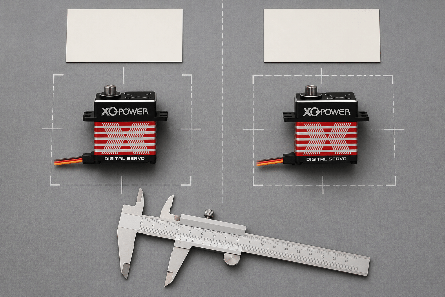
XQ-BLS8125D: compact brushless servo for lower torque requirements
The XQ-BLS8125D brushless servo is listed with 25 kg.cm torque at 8.4 V, 22 kg.cm at 7.4 V, and 18 kg.cm at 6.0 V. Its listed operating speed is 0.07 sec/60° at 8.4 V. The page identifies a 6.0–8.4 V range, a brushless motor, a toughened stainless-steel gear set, a full CNC aluminum case, and waterproof protection.
This makes it a candidate for compact mechanisms where the measured load fits the published torque and voltage conditions. The final choice still depends on duty cycle, mounting, power delivery, and environmental requirements.
RS8125D: an RS485 option for distributed control
The RS8125D RS485 brushless servo is listed with 25 kg.cm torque at 8.4 V, 22 kg.cm at 7.4 V, and 18 kg.cm at 6.0 V. Its product page identifies RS485 command-bus control, a 0.07 sec/60° operating-speed value at the stated product condition, and waterproof protection.
For a multi-node system, the communication interface becomes part of the selection process. Confirm the controller’s protocol settings, wiring, node configuration, power distribution, and model-specific documentation before integration. A servo should not be chosen for RS485 simply because a system needs fewer signal wires; the complete network design must also be validated.
RS460: an integrated Modbus RS485 smart servo
The RS460 Modbus RS485 smart robot servo is listed with 58 kg.cm torque at 12 V and 360° continuous absolute position control with 12-bit resolution. The product page also lists three operating modes—servo position, DC gear motor, and constant torque—and feedback fields including position, temperature, speed, voltage, and current.
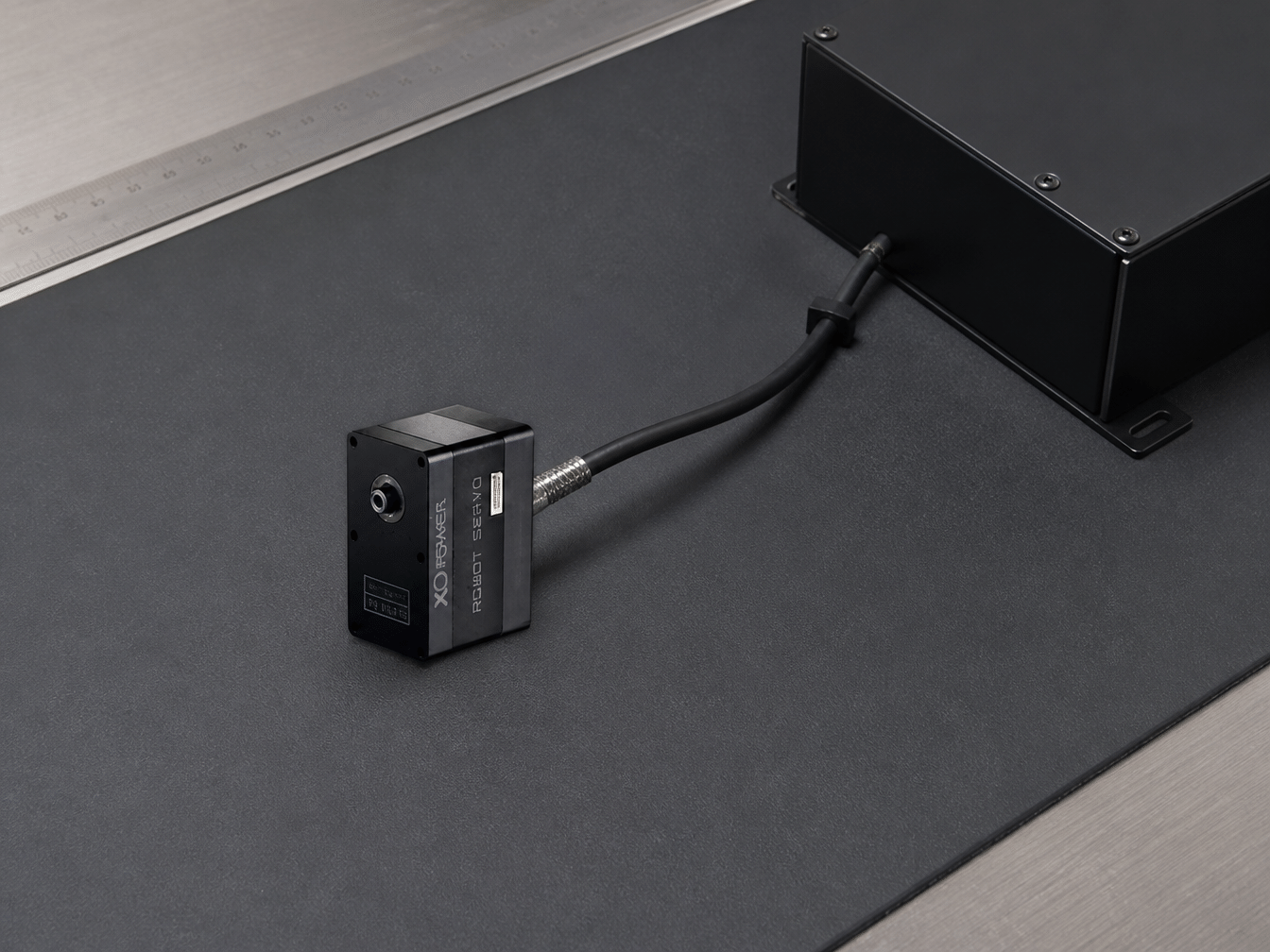
These features may be relevant when an application needs an integrated actuator and serial communication architecture. They do not remove the need to check the required load, operating cycle, controller compatibility, thermal conditions, and mechanical interface for the actual project.
S9150D: a higher-torque industrial brushless servo
The S9150D industrial brushless servo is listed with 180 kg.cm at 16.8 V, 160 kg.cm at 12.6 V, and 115 kg.cm at 8.4 V. Its page lists 0.14 sec/60° speed at 16.8 V, an 8.4–16.8 V range, a CNC aluminum case, toughened steel gears, a 25T output with a 9.95 mm diameter, and splash-resistant protection.
This model class may be considered when the measured load is substantially higher, but the listed peak or stall value must still be separated from the continuous requirement. For an AGV or robotic joint, validate the complete torque curve, load duration, temperature rise, mounting, power supply, and controller behavior before production use.
Validate heat and duty cycle before production
Thermal behavior is part of high torque servo sizing. A servo that completes a short movement successfully may behave differently when it holds torque, repeats the same movement frequently, or operates in a warm enclosure.
A practical validation plan should define:
- The load torque and direction during each motion phase
- The movement speed and acceleration
- The time under load and rest interval
- Supply voltage measured at the servo under load
- Ambient and enclosure temperature
- Servo case temperature and any available feedback data
- Number of cycles and test duration
- Mounting structure, linkage, and cooling condition
- Any position error, noise, vibration, or current increase
Do not describe a model as suitable for continuous duty simply because it has a high stall rating. If the application involves a valve, AGV steering, a robotic joint, or another mechanism that holds load for long periods, ask for model-specific operating conditions and test data.
Check the mechanical interface before ordering samples
Torque calculations can still fail when the mechanical interface is wrong. Before ordering a sample, verify the mounting pattern, output spline or shaft, horn or hub compatibility, allowable radial and axial loading, alignment, and clearance through the complete range of motion.
A rigid bracket, correct output engagement, and aligned linkage help prevent additional loads that were not included in the original calculation. The servo motor mounting guide covers flange, spline, shaft, coupling, alignment, and structural-support considerations.
For a sample request, include the model under review, required torque, voltage, speed, duty cycle, mounting constraints, communication interface, feedback needs, environmental conditions, and the test criteria you will use for acceptance. This gives the engineering team enough context to discuss a suitable standard model or an OEM/ODM route.
Use the controller and protocol as selection criteria
A servo is part of a control system, not an isolated motor. Confirm whether the application requires PWM, RS485, CAN, or another documented interface. Then verify signal settings, wiring, power conditions, node addressing, feedback fields, and fail-safe behavior for the selected model.
For distributed automation, RS485 or Modbus may be relevant, but the controller and network still need to be tested under the actual cable length, node count, update rate, electrical noise, and power arrangement. For UAV or safety-related systems, application suitability should be reviewed at the complete system level rather than inferred from a general product category.
A concise high-torque servo sizing checklist
Before selecting a model for an AGV or robotic joint, confirm:
- The load torque is measured or calculated at the output shaft.
- Continuous, peak, and stall requirements are separated.
- Voltage and current are checked at the servo under load.
- Speed, acceleration, and duty cycle are defined.
- Thermal limits are evaluated under repeated operation.
- Mounting, alignment, spline, shaft, and linkage interfaces are compatible.
- The controller and communication protocol match the exact model.
- Feedback requirements are documented and testable.
- A sample-validation plan defines pass/fail criteria.
- The final model is confirmed against its current datasheet and application limits.
High-Torque Servo Sizing FAQ
Stall torque is measured when the servo output is prevented from rotating under a defined test condition. Continuous torque is the load a servo can sustain over a specified duty cycle while remaining within its electrical, mechanical, and thermal limits. Stall torque should not be treated as a continuous operating rating without confirming the applicable conditions.
Start by calculating the output load torque from force and effective lever arm. Then include acceleration, friction, transmission efficiency, shock loading, speed, duty cycle, voltage, mounting stiffness, and thermal conditions. Compare the calculated continuous and peak requirements with model-specific data, and validate the selected servo using the AGV’s actual steering or drive cycle.
Not automatically. Continuous operation depends on the exact voltage, speed, load duration, rest interval, ambient temperature, mounting, cooling, and product-specific thermal limits. A maximum or stall torque value alone does not confirm continuous-duty capability.
The answer depends on the joint’s measured torque, speed, duty cycle, voltage, mechanical envelope, feedback needs, and communication interface. XQ-POWER offers different product classes, including the 25 kg.cm BLS8125D, the 58 kg.cm RS460 Modbus RS485 smart servo at 12 V, and the higher-torque S9150D industrial servo. Review the exact datasheet and validate the model under the intended joint load before production use.
Choose an RS485 model when the system requirements call for a documented serial-bus architecture, distributed nodes, or model-specific feedback and configuration functions. Confirm the controller protocol, wiring, node arrangement, power distribution, and available feedback for the exact servo variant before integration.
Provide the required torque, voltage, speed, duty cycle, load profile, mounting dimensions, output spline or shaft requirement, controller and communication protocol, feedback needs, environmental conditions, and sample acceptance criteria. This helps the XQ-POWER engineering team evaluate a standard model or discuss OEM/ODM customization.
Need help with servo selection?
Share your load torque, voltage, speed, duty cycle, mounting constraints, communication protocol, and application environment with the XQ-POWER engineering team. The team can review the application and recommend a suitable servo or discuss an OEM/ODM solution. For sample and technical inquiries, use the XQ-POWER contact page.