
Because the gear train is the mechanical path between the motor and the output shaft. It must transmit torque, support acceleration and reversal, and tolerate the load cycle imposed by the application. In an RC vehicle, a gear train may see rapid steering corrections, drivetrain shock, and repeated impacts. In a robot joint or automation mechanism, it may see sustained holding torque, frequent reversals, and thermal cycling.
Servo gear strength is therefore more than a material label. It depends on the gear material, tooth geometry, module, face width, shaft support, alignment, lubrication, temperature, load duration, impact profile, and manufacturing quality. A stronger material can improve resistance to tooth deformation or wear, but it does not make a gear train immune to overload, misalignment, contamination, or fatigue.
XQ-POWER’s published product pages show model-specific choices such as toughened stainless steel gears on the BLS8125D, a toughened steel gear train on the RS460, and steel gears on the S9150D, S9450D, and S9750D. These examples show why the gear design must be matched to the servo’s torque class and application; they should not be extended into an unqualified statement that every model uses the same gear material or construction.
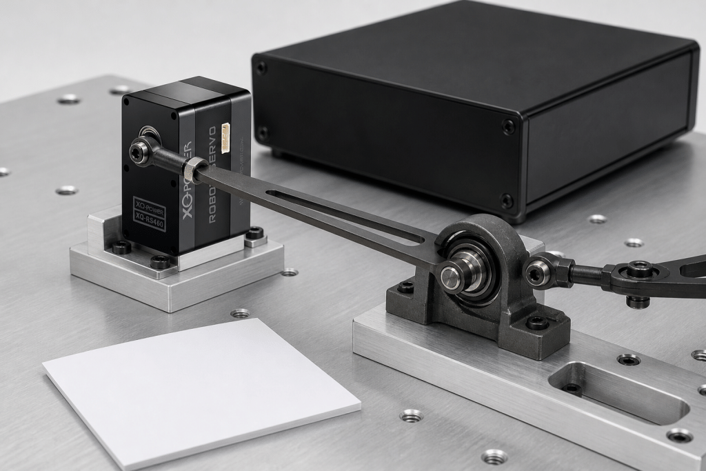
What does servo gear strength mean?
Servo gear strength is the ability of the gear train to transfer the required torque without unacceptable tooth breakage, plastic deformation, excessive wear, backlash growth, or loss of functional accuracy under a defined operating cycle.
Several failure modes can occur in a gear train:
- Tooth bending: A tooth root can experience high bending stress when torque or impact load rises.
- Surface wear: Repeated sliding and contact stress can remove material from the tooth flank.
- Pitting or surface fatigue: Repeated contact cycles can create local surface damage under high stress.
- Plastic deformation: An overload can permanently alter a tooth profile or bearing surface.
- Backlash growth: Wear, deformation, shaft movement, or bearing clearance can increase lost motion.
- Tooth fracture: A severe shock, fatigue crack, or pre-existing defect can cause a tooth to chip or break.
- Misalignment damage: Incorrect assembly can concentrate load on part of the tooth width and accelerate wear.
The relevant question is not simply “Is the gear metal?” It is “Can the complete gear train handle the required torque, speed, duty cycle, shock, temperature, and alignment conditions?”
Why can’t a high-torque servo use any gear material?
Gear material affects density, strength, hardness, wear behavior, friction, manufacturability, and cost. The correct material depends on the torque class and operating cycle.
| Gear option | Potential advantages | Engineering limits to consider |
|---|---|---|
| Polymer gear | Low mass, low noise, and useful damping | May be unsuitable for high shock, high temperature, or high continuous torque; the exact polymer and geometry matter |
| Steel gear | High strength and useful wear resistance when properly designed | Higher mass and possible noise; lubrication, alignment, hardness, and tooth geometry remain important |
| Toughened stainless steel gear | Can provide a corrosion-resistant metal gear option with useful strength and wear behavior | “Stainless steel” does not by itself define hardness, heat treatment, fatigue life, or allowable continuous load |
| Titanium or other specialty alloy | May offer a specific strength-to-weight or corrosion trade-off in a selected design | Must be confirmed for the exact model; no universal alloy or grade should be assumed |
The published XQ-POWER pages identify the following examples:
- BLS8125D: The product information lists a toughened stainless steel gear set, a full CNC aluminum case, and dual ball bearings.
- RS460: The product information lists a toughened steel gear train, a CNC aluminum case, dual industrial ball bearings, and an 8 mm output shaft.
- S9150D: The product information lists a steel gear train and a CNC aluminum case.
- S9450D: The product information lists a steel gear, eight ball bearings, and an aluminum CNC case.
- S9750D: The product information lists a steel gear, ten ball bearings, and an aluminum CNC case.
The accessible product pages do not establish a universal titanium gear range, a common heat-treatment grade, a tooth-hardness value, or a single fatigue-life rating for every XQ-POWER servo. Those details should be confirmed from the exact model specification when they are important to the design.
How does gear geometry affect torque capacity?
Material is only one part of gear strength. Geometry determines how the tooth carries force and how that force is distributed through the gear train.
- Module or tooth size: Larger teeth can carry greater force in a given design, but size alone does not define capacity.
- Tooth count: Tooth count affects ratio, contact conditions, undercut risk, and the dimensions available inside the housing.
- Face width: A wider tooth face can distribute load across a larger area when alignment is controlled.
- Pressure angle and tooth profile: These affect radial force, contact stress, sliding, and torque transmission.
- Gear ratio: A higher reduction ratio can increase output torque while changing speed, efficiency, reflected inertia, and the number of loaded tooth contacts.
- Center distance and alignment: Incorrect center distance or shaft alignment can create uneven contact and local overload.
- Bearing support: Bearing stiffness and clearance influence how the gear remains aligned under torque.
- Output-shaft and housing rigidity: Gear geometry cannot compensate for housing deflection or output support that allows the gear mesh to move.
For a compact high-torque servo, the gear train, bearings, output interface, and case must be designed as one load path. A stronger gear placed in a flexible or misaligned structure may still produce poor service life.
What role can heat treatment play?
Heat treatment can change a gear’s hardness, toughness, wear resistance, and residual stress. In a suitable design, the surface may be made more resistant to contact wear while the core retains enough toughness to resist shock. The correct process depends on the alloy, tooth size, geometry, required hardness profile, and manufacturing route.
However, a heat-treatment claim should be tied to a documented model and process. The accessible product pages identify gear materials for several models but do not publish a universal heat-treatment method, hardness value, case depth, or fatigue-life result for the full product line. The article therefore treats heat treatment as an engineering design variable rather than assigning an unverified specification to every XQ-POWER servo.
When a project requires formal gear-life analysis, request the exact model’s material and inspection documentation. The relevant review should consider:
- Material grade and batch control
- Hardness or hardness profile, if specified
- Tooth geometry and manufacturing tolerance
- Surface finish and contact pattern
- Lubricant type and service-temperature range
- Torque, speed, duty cycle, and shock profile
- Permitted backlash and wear limit
- Inspection method after endurance testing
Why are metal gears useful in RC vehicles?
RC vehicles can expose a servo to short, high-amplitude loads. Steering linkages may hit the ground, wheels may change direction under traction, and suspension or drivetrain impacts can transmit shock through the mechanism. A polymer gear can be appropriate in a lightweight, low-load, low-noise design, but a metal gear train may be better suited to a selected high-load or high-impact duty cycle.
That does not mean a metal gear is automatically the correct choice for every RC vehicle. Metal gears may add mass, transmit more noise, and still fail if the mechanism creates an impact beyond the design envelope. The servo should be selected using the wheel load, linkage leverage, steering angle, speed, terrain, impact profile, duty cycle, and power supply.
For a compact brushless option, the BLS8125D 25 kg·cm servo publishes 25 kg·cm at 8.4 V and identifies a toughened stainless steel gear set. That published gear description supports discussion of the model’s construction; it does not establish an unlimited impact rating or a universal service-life guarantee.
How do high-torque robot servos load their gears?
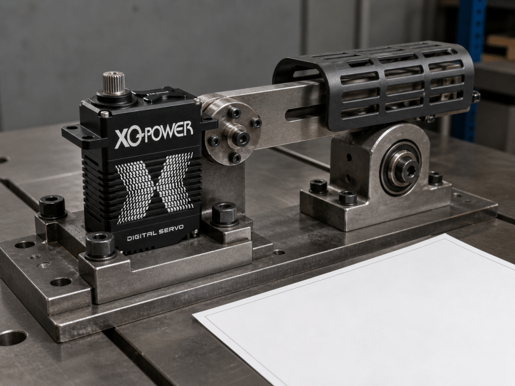
A robot joint may produce a large static torque while also reversing direction, accelerating an inertia, stopping at a limit, or holding a load against gravity. The gear train experiences more than the nominal external load:
- Motor torque multiplied through the reduction ratio
- Reaction torque from the housing and mounting structure
- Acceleration torque from the reflected inertia
- Friction from bearings, seals, linkages, and external mechanisms
- Impact torque from hard stops or collisions
- Thermal effects from sustained current and repeated motion
- Alignment error between the servo and the driven joint
The S9150D 180 kg·cm industrial brushless servo page lists a steel gear train, CNC aluminum case, and 180 kg·cm peak stall torque at 16.8 V. The S9450D page lists a steel gear and 700 kg·cm class peak stall torque at 30 V. The S9750D page lists a steel gear and peak stall torque points of 850 kg·cm at 24 V, 920 kg·cm at 28 V, and 980 kg·cm at 30 V.
These are specified peak or stall conditions, not automatic continuous-load ratings. A robot design must separate holding torque, acceleration torque, impact torque, and continuous thermal operation. The gear train must be evaluated against the actual torque-time profile, not only the largest number in a product title.
How can a gear train wear even when the torque is below the peak value?
A gear can wear under a nominal torque that is below the listed peak value if the cycle is long, the speed is high, the temperature is elevated, lubrication is inadequate, or alignment is poor. A repeated moderate load may create more cumulative damage than a short isolated peak.
- High repetition count with insufficient cooling
- Frequent direction reversals
- Continuous holding near a high load
- High gear speed or rapid acceleration
- Inadequate or displaced lubrication
- Contamination or abrasive particles
- Housing or mounting deflection
- Excessive output-shaft radial or axial loading
- Incorrect gear mesh or bearing seating
- Temperature outside the model’s documented range
A torque rating does not describe every combination of speed, temperature, and duty cycle. Use the published value with its voltage and test condition, then validate the complete operating cycle.
How do lubrication and temperature affect gear life?
Lubrication reduces friction and helps separate contacting surfaces. Its performance depends on viscosity, film strength, compatibility with the materials and seals, operating temperature, speed, and the quantity and distribution of lubricant.
Low temperature can increase lubricant viscosity and startup resistance. High temperature can reduce viscosity, accelerate oxidation, or change the lubricant’s ability to maintain a protective film. Neither condition should be assessed from a generic lubricant label alone.
For a demanding application, define:
- Minimum and maximum operating temperatures
- Startup temperature and warm-up profile
- Gear speed and reversal rate
- Load torque and duration
- Lubricant type and application method, if documented
- Sealing and contamination conditions
- Inspection interval and acceptable wear limit
The correct lubricant for one model or environment should not be assumed for another. If the product documentation does not specify the lubricant or service interval, request model-specific guidance before changing the internal grease.
How do housing and output support affect gear strength?
The gear train transfers torque through shafts, bearings, housing features, and the output interface. A stiff gear can still experience uneven contact if the housing or bearing support deflects under load.
The RS460 product page describes a CNC aluminum case, toughened steel gear train, dual industrial ball bearings, and an 8 mm heavy-duty output shaft. The S9150D page describes a CNC aluminum case and steel gear train. These details indicate that the load path includes more than the gear material itself.
The mounting structure should also prevent external bending and radial loads from being transferred into the output bearings beyond the documented allowance. For robot joints, use an independent bearing, shaft, or structural support when it is responsible for carrying the main external bending moment. The servo should provide the required drive torque within its specified mechanical arrangement.
See the servo mounting, spline, and shaft guide before selecting a horn, coupling, bracket, or output connection.
How should a gear-strength test be designed?
A useful test reproduces the torque-time profile and failure modes of the application. A short stall test alone cannot represent a robot joint, RC vehicle, or production actuator that reverses thousands of times.
Static torque test
Apply a controlled torque at the selected voltage and measure output position, current, housing movement, and temperature. Keep the test within the approved product and laboratory limits. Record whether the torque is a short peak, a hold, or a continuous duty point.
Repeated-cycle test
Command the actual motion profile with representative acceleration, speed, reversal, dwell, and rest intervals. Record current, temperature, position error, backlash, noise, and output motion throughout the cycle.
Shock or transient test
If the application includes wheel impacts, hard stops, collisions, or landing loads, define the transient duration and peak torque. Use a guarded fixture and a controlled input. Do not infer a safe shock rating from a material name.
Temperature test
Repeat the motion cycle at the expected minimum and maximum temperatures. Measure startup behavior, running current, case temperature, position accuracy, and backlash after the cycle.
Inspection after cycling
Inspect teeth, shafts, bearings, housing fasteners, output splines, horns, and lubricant condition. Compare backlash, tooth contact, noise, current, and position error with the initial baseline.
The Technical Guide provides related guidance on sizing, thermal management, environmental protection, and motion-control integration.
How should users interpret published torque data?
Published torque should always be read with its voltage, speed, test condition, and duty-cycle context. The stall-versus-continuous torque guide explains why a peak or stall number is not automatically a continuous operating rating.
For a gear-strength decision, request or record:
- Model and exact variant
- Supply voltage
- Peak, stall, rated, or continuous torque definition
- Speed and output position
- Load duration and repetition rate
- Ambient and case temperature
- Mounting and output-support arrangement
- Gear and bearing construction
- Lubrication information
- Backlash and wear limits
- Endurance or cycle-test conditions
This approach prevents a high-torque label from being used as a substitute for a mechanical load calculation.
Can metal gears fail?
Yes. Metal gears can chip, deform, wear, or fracture when the applied load, impact, fatigue cycle, temperature, lubrication, alignment, or manufacturing defect exceeds the design envelope. A metal gear train generally provides a different strength and wear trade-off from a polymer gear, but “metal” is not an absolute no-failure statement.
The same applies to stainless steel or any specialty alloy. The grade, hardness, geometry, heat treatment, surface finish, support, and load cycle all matter. For production-critical applications, validate the complete servo and mechanism rather than relying on the material name alone.
Direct answer for RC, robotics, and automation projects
XQ-POWER focuses on gear design because the gear train determines how motor torque reaches the output shaft and how the actuator behaves under repeated, reversing, and shock loads. Published examples show toughened stainless steel gearing on the BLS8125D, toughened steel gearing on the RS460, and steel gears on the S9150D, S9450D, and S9750D.
The right choice still depends on the exact model and duty cycle. Gear material must be evaluated together with tooth geometry, support bearings, case rigidity, lubrication, temperature, alignment, external loading, and impact conditions. A project should confirm any titanium alloy, heat-treatment grade, hardness value, fatigue life, or allowable continuous load from the selected model’s documentation or engineering team.
Servo Gear Strength FAQ
The gear train transfers motor torque to the output shaft and may experience steering corrections, acceleration, reversals, and impact loads. Gear strength affects tooth deformation, wear, backlash, and the ability to maintain the required output motion under the defined duty cycle.
The accessible product pages show model-specific construction rather than one universal gear specification. BLS8125D lists a toughened stainless steel gear set; RS460 lists a toughened steel gear train; S9150D, S9450D, and S9750D list steel gears. The gear material for another model should be confirmed from its exact product documentation.
No. Stainless steel describes a material family, not an unlimited load rating. Gear grade, hardness, geometry, support, lubrication, alignment, temperature, impact, and repeated fatigue cycles all affect reliability. A stainless steel gear can still wear, deform, chip, or fracture under unsuitable conditions.
The accessible product information used for this article does not establish a universal titanium gear range, heat-treatment grade, tooth hardness, or fatigue-life rating for every model. Request the exact model’s specification or engineering documentation when those details are required.
No. A peak or stall torque value describes a defined test condition. Continuous gear loading depends on voltage, speed, duty cycle, temperature, cooling, mounting, lubrication, and the complete mechanism. Use the torque value with its test condition and validate the required operating cycle.
Run a controlled static torque test, representative repeated-cycle test, transient or shock test where relevant, and temperature test. Record current, position error, temperature, backlash, noise, and output motion, then inspect teeth, bearings, output interfaces, housing, and lubricant against the initial baseline.
Need help selecting a gear train for your application?
Send the target torque, voltage, speed, duty cycle, impact profile, temperature range, mounting arrangement, output interface, and application type to the XQ-POWER engineering team. The team can discuss the appropriate model, sample testing, and OEM/ODM options for a defined motion-control requirement.