
A high torque servo motor is a good fit when a mechanism must produce strong output force, absorb repeated load changes, or hold a position against a substantial mechanical moment. For a 1/5 scale RC buggy, the priority is steering authority under bump and shock loads. For a winch, it is sustained pulling torque. For a robotic arm, it is repeatable holding and positioning across multiple joints. In every case, match the servo’s operating voltage and physical mounting dimensions to the mechanical system before deployment.
At-a-Glance Key Takeaways
- 1/5 scale RC buggy: Use a high torque servo for steering systems that see repeated bump impact, tire resistance, and shock loading.
- Winch system: Evaluate sustained output torque, duty cycle, line-pull geometry, and thermal margin rather than relying on a peak label alone.
- Robotic arm: Size each joint for gripping, lifting, acceleration, and holding torque; multi-joint systems also require coordinated mechanical and electrical integration.
- Every application: Confirm operating voltage, mounting dimensions, output interface, clearance, and controller compatibility before ordering.
- Torque terminology matters: Stall torque is not automatically the same as continuous torque or continuous stall torque.
- Model review: XQ-POWER’s live high-torque category includes model families such as S9150D and S9750 variants; final selection requires model-specific documentation and engineering validation.
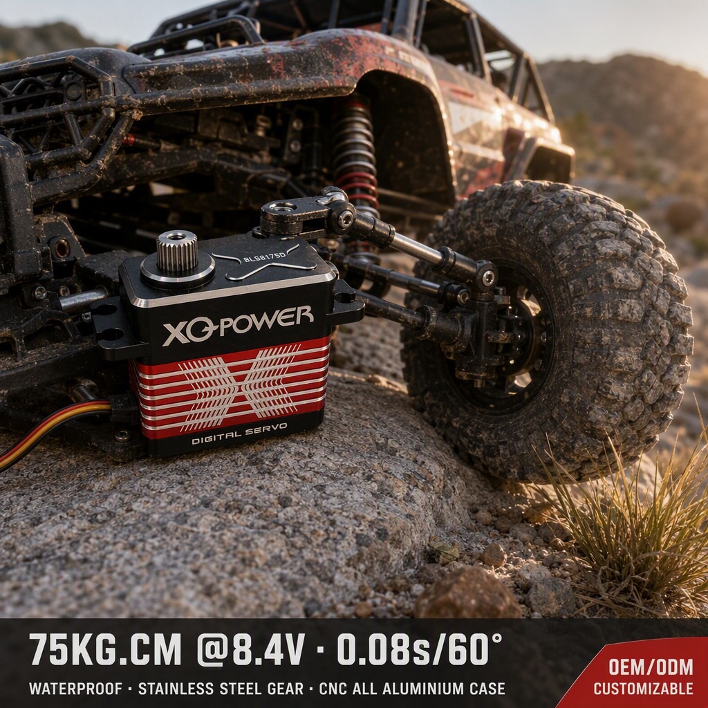
When Do You Need a High-Torque Servo?
The right servo is determined by the load profile, not by the product label alone. A mechanism may need high torque because it must overcome a long lever arm, maintain force while stationary, absorb repeated impacts, move a high-inertia assembly, or hold a load during a long duty cycle.
A practical first step is to define four conditions:
- Required output torque: What moment must the shaft produce at the driven mechanism?
- Operating profile: Is the load intermittent, repetitive, or continuously held?
- Power condition: What operating voltage will the controller deliver under real load?
- Mechanical interface: Can the servo body, mounting pattern, output interface, and linkage fit the assembly without interference?
The XQ-POWER high torque servo motor category is a useful starting point for comparing application-oriented model families. It should be followed by a review of the exact product specification, load profile, operating voltage, and mounting arrangement.
High-Torque Servo for 1/5 Scale RC Buggy Steering
A 1/5 scale RC buggy places much greater demand on steering hardware than a lightweight model. Large tires, high grip, uneven terrain, suspension movement, and steering impacts can create rapid changes in load at the servo output. The steering system may also need to maintain position while the vehicle is stationary or while one wheel encounters a high-resistance obstacle.
A high torque servo is useful in this application because it can provide stronger steering authority and more usable margin against bump impact and shock load. The selection should not be based on torque alone. Check the servo’s response speed, operating voltage, output interface, mounting dimensions, linkage geometry, and the mechanical strength of the servo tray and steering components.
The servo must be mounted so that the steering linkage moves freely through its complete range. Binding can make a capable actuator behave like an undersized one because the motor is forced to work against unnecessary friction. Also check whether the steering load is transmitted directly into the output bearing or through a suitable linkage arrangement.
For a brushless option, compare the relevant brushless servo motor models against the buggy’s voltage, space, response, and duty-cycle requirements. Do not assume that every brushless model uses the same output interface or mounting pattern.
High-Torque Servo for Winch Load-Pulling Systems
A winch application is defined by its pulling requirement. The servo must generate enough output torque to rotate the drum, spool, or geartrain while the mechanism pulls a payload. The required torque changes with the effective drum radius, line position, gearing, friction, acceleration, and payload condition.
The important distinction is between a brief peak event and sustained output. A winch may pull slowly for an extended period, which means the servo’s heat generation and duty cycle must be evaluated alongside its torque requirement. A model that can produce a high short-duration value may still be unsuitable for a long pull if the thermal path, power supply, or mechanical reduction is not adequate.
Before selecting a high torque servo for a winch, document:
- Payload force and expected line tension;
- Effective drum radius at the beginning and end of the pull;
- Gear ratio and transmission efficiency;
- Pulling speed and acceleration;
- Expected hold duration and rest intervals;
- Operating voltage at the servo terminals;
- Mounting dimensions and shaft or coupling arrangement.
If the winch must hold a payload after movement stops, evaluate the holding load separately from the movement load. The controller, gearbox, brake arrangement, and mechanical structure may each affect how long the actuator must maintain torque.
High-Torque Servo for Multi-Joint Robotic Arms
A robotic arm converts servo torque into joint force through the link length and joint geometry. A joint near the base may see the combined effect of several downstream links, tools, and payloads. A wrist joint may have a smaller total load but still require precise holding torque during gripping, lifting, or tool positioning.
A high torque industrial servo motor can support these tasks when the model is correctly matched to the joint’s continuous and peak load profile. The engineering calculation should include payload mass, center-of-gravity offset, link length, acceleration, friction, transmission losses, and the torque required to hold the arm in its most demanding pose.
Multi-joint systems also need a system-level review. Each servo must fit its joint envelope, use a compatible voltage and controller, and provide an output interface that matches the linkage. Wiring, controller capacity, motion synchronization, and maintenance access matter as much as the rated torque label.
For projects that need application-level guidance, the XQ-POWER solutions page describes motion-control use cases spanning robotic arms and UAV-related actuation. Treat the page as a system-integration reference, then confirm the final model and operating conditions with the engineering team.
Critical Matching Factors: Operating Voltage and Mounting Dimensions
Operating voltage is a selection constraint, not a detail to address after purchase. Torque and speed can change with the supplied voltage, while the controller, wiring, connector, and power source must all be able to support the intended operating point. Confirm the permitted voltage range from the exact model documentation and verify the voltage at the servo under load.
Physical fit is equally important. Before mounting a servo to a shaft or bracket, verify:
- Body length, width, and height;
- Mounting-hole pattern and fastener access;
- Mounting face, flange, and locating features;
- Output spline or shaft interface;
- Allowable radial and axial loading;
- Linkage clearance throughout the full movement range;
- Cable exit direction and service access.
The servo motor mounting guide explains why flange, spline, shaft, alignment, and structural support must be evaluated as one mechanical assembly. Do not infer dimensions or output compatibility from a similar-looking model.
A rigid bracket is also part of the torque path. If the mounting plate flexes, the servo may appear to lose positioning accuracy even when its internal feedback is functioning correctly. For an RC buggy, inspect the servo tray and steering linkage. For a winch, inspect the drum support and coupling. For a robotic arm, inspect the joint housing, bearing support, and transmission alignment.
Understand Stall Torque vs. Continuous Torque
The term stall torque describes torque measured when the output is prevented from rotating under a defined test condition. It is useful for understanding a performance point, but it does not automatically define a safe continuous operating load.
Continuous torque describes the load a servo can sustain over a specified duty cycle while remaining within its electrical, mechanical, and thermal limits. Continuous stall torque should be treated carefully because its meaning depends on the supplier’s test method and stated operating conditions. Always ask what voltage, duration, temperature, output position, and duty cycle apply to the quoted value.
The stall torque explanation provides a useful framework for separating peak measurements from continuous application requirements. The basic load relationship is:
Required load torque = force × effective lever arm
The final selection may also need acceleration torque, friction, transmission efficiency, shock loading, and a project-specific safety margin. Do not apply one fixed margin to every design. The appropriate margin depends on load uncertainty, impact severity, thermal limits, and the consequence of losing position.
For a 1/5 scale buggy, peak steering shock and tire resistance may dominate. For a winch, continuous pull and hold duration may dominate. For a robotic arm, the worst joint pose and acceleration may dominate. These are different torque problems even when all three projects use a high torque servo.
What Are the Advantages of a Brushless High-Torque Servo?
A brushless servo motor uses electronic commutation rather than mechanical brushes. This changes the maintenance and performance considerations, but it does not remove the need for correct sizing. A brushless design still must be evaluated for voltage, torque, speed, feedback, mechanical interface, duty cycle, controller compatibility, and the complete load profile.
The practical reasons engineers may consider a brushless servo include reduced brush-related maintenance, compatibility with electronically controlled motion systems, and suitability for applications that require repeated operation. Whether those benefits matter for a specific RC buggy, winch, or robotic arm depends on the project’s operating cycle and integration requirements.
A brushless model is not automatically the right answer for every mechanism. Compare the available feedback, communication protocol, output interface, mounting dimensions, and documented performance conditions. For B2B projects, also request the documentation needed for validation, production testing, and OEM/ODM review.
Practical Servo Selection Checklist
Use this checklist before choosing among high torque servo motors:
Load and motion
- Calculate the required servo motor torque at the actual output interface.
- Separate peak, holding, and continuous load conditions.
- Include lever arm, friction, acceleration, transmission loss, and shock load.
- Identify the worst position in the mechanism, not only the easiest test position.
Power and control
- Confirm the operating voltage range for the exact model.
- Check power-supply current capacity, wiring, connectors, and controller limits.
- Confirm PWM, serial bus, or other required control interface.
- Define the feedback data and alarms needed during commissioning.
Mechanical integration
- Match body dimensions and mounting-hole pattern.
- Verify spline or shaft compatibility before machining mating parts.
- Check radial and axial loading, alignment, clearance, and bracket stiffness.
- Ensure the linkage or coupling can reach the full intended travel without binding.
Validation
- Test at the actual voltage and representative load.
- Record position, current, temperature, speed, and operating time where available.
- Repeat the test for the expected duty cycle rather than one short movement.
- Inspect backlash, fasteners, couplings, and mounting structure after endurance testing.
- Mark any item requiring confirmation from the XQ-POWER engineering team before production deployment.
Frequently Asked Questions
It can be suitable when the steering load, operating voltage, mounting dimensions, output interface, response requirement, and shock load are matched to the model. Check the full steering assembly rather than selecting from a torque label alone.
A suitable winch servo must be evaluated for sustained output torque, drum radius, gear ratio, pulling speed, hold duration, voltage, and heat management. Peak stall torque alone does not prove that the servo can complete a long pull.
Calculate the joint moment from payload force and the effective lever arm, then include link mass, acceleration, friction, transmission loss, and the worst arm position. Verify the model’s voltage, mounting dimensions, output interface, and continuous duty requirements.
No. They may refer to different test conditions or application interpretations. Ask the supplier to define the voltage, duration, temperature, output position, and duty cycle behind each torque value.
Confirm the body dimensions, mounting pattern, output spline or shaft, coupling geometry, allowable loading, alignment, fastener arrangement, and clearance through the complete motion range. Use the exact model documentation before machining a mating component.
No model should be treated as a universal solution. S9150D and S9750 are model references visible in XQ-POWER’s high-torque product resources, but the correct choice depends on the project’s voltage, torque profile, physical envelope, controller, duty cycle, and mechanical interface. Confirm final suitability with model-specific documentation and engineering review.
Conclusion: Match the Servo to the Real Mechanism
A high torque servo is most useful when it is selected around the real application rather than a single headline specification. A 1/5 scale RC buggy needs steering authority against repeated impact. A winch needs controlled torque over a sustained pull. A robotic arm needs joint torque that remains useful across gripping, lifting, acceleration, and holding positions.
For all three, confirm operating voltage and physical mounting dimensions before deployment. Then separate stall torque from continuous requirements, check the output interface and structural load path, and validate the complete mechanism under representative conditions.
Browse the high torque servo motors category for project-oriented starting points. For a specific load profile, voltage, mounting arrangement, or OEM/ODM requirement, ask XQ-POWER to review the application before production selection.
Engineering validation note: Final model suitability, continuous operating limits, voltage selection, mounting compatibility, and application safety margin must be confirmed against the exact product documentation and the project’s measured load profile before production deployment.