
Overview
In UAV programs, engineers rarely decide actuator control interfaces at the beginning of the design cycle. Instead, they adjust these interfaces as the aircraft structure, control logic, and integration requirements evolve.
At first glance, choosing between PWM, CAN, or digital control looks like a simple technical decision. In practice, it depends heavily on wiring layout, timing constraints, and available processing resources inside the flight controller.
Because of this, UAV actuator control interfaces often evolve alongside the platform rather than staying fixed.
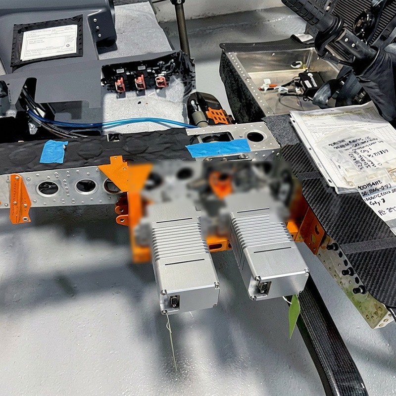
When interface choices start to matter
Early UAV prototypes usually rely on PWM because engineers can implement it quickly and debug it easily.
However, problems start to appear when the system scales.
Engineers begin to face several practical issues:
- wiring becomes harder to route across larger airframes
- timing differences appear between multiple actuators
- debugging takes longer because the system provides no feedback
At this stage, interface design stops being a simple component choice and becomes a system-level constraint.
Transition from PWM to CAN-based control
Most UAV platforms move from PWM to CAN when they enter integration or flight test phases.
This shift usually happens for practical reasons rather than performance upgrades.
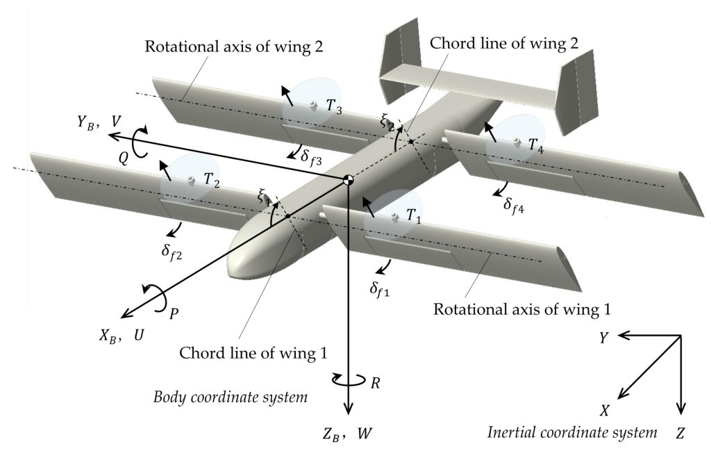
For example, when engineers test VTOL platforms, they often observe:
- left and right actuators respond at slightly different times
- flight controller cannot detect actuator health in real time
- wiring harness becomes heavy and complex
To solve these issues, teams redesign UAV actuator control interfaces around CAN-based communication.
What engineers gain with CAN
When engineers introduce CAN into a UAV system, they change how they interact with the actuators.
Instead of sending blind position commands, they can now:
- read actuator position in real time
- monitor temperature and current draw
- detect faults directly from each node
This shift helps engineers debug problems faster and tune the system more precisely.
At the same time, engineers must also manage bus load and message timing, which adds a new layer of system design work.
Real UAV systems rarely use a single interface
In real aircraft, engineers almost never rely on a single actuator interface type.
Instead, they combine multiple methods:
- PWM for simple secondary functions
- CAN for primary flight control surfaces
- digital ESC protocols for propulsion systems
This hybrid structure grows naturally over time as teams integrate subsystems from different development stages.
A typical problem in VTOL transition flight
VTOL platforms often expose interface limitations during transition phases.
When engineers use PWM for multiple tilt actuators, they sometimes see small timing mismatches.
These mismatches can cause:
- uneven thrust during transition
- small oscillations in pitch or roll
- unstable mid-transition attitude behavior
To fix this, engineers usually move toward synchronized network-based control.
https://dronecan.github.io/https://dronecan.github.io/
Interface problems usually come from system design
In most UAV projects, interface issues rarely come from the communication protocol itself.
Instead, engineers usually trace problems back to:
- flight control loop timing
- power noise affecting signal integrity
- structural flex affecting sensor alignment
For this reason, engineers treat actuator interface design as part of system architecture, not just electrical design.
Summary
UAV actuator control interfaces evolve together with the aircraft they support. Engineers start with simple PWM systems, but they gradually move toward networked architectures as complexity increases.
In most real UAV programs, interface design reflects system maturity more than technology preference.
Powering Innovation
Contact XQ-power’s product specialist to recommend suitable motor or servo for your product.