
No. A potentiometer servo is not automatically more stable at center than a magnetic-sensor servo, and a magnetic sensor is not automatically more accurate. Center stability is a system result.
For an RC helicopter, the center position depends on the position sensor, feedback electronics, control algorithm, gear train, output spline or horn, linkage stiffness, mechanical backlash, vibration, temperature, calibration, and the load profile of the cyclic or tail mechanism. A sensor with good nominal resolution can still show center drift if the output connection is loose, the gear train has backlash, the algorithm is poorly tuned, or the sensor is affected by temperature and installation error.
A potentiometer measures position through mechanical electrical contact. Its behavior can be predictable in a well-designed and well-calibrated servo, but the contact system is subject to wear, contamination, friction, and electrical noise. A magnetic sensor measures position without a sliding electrical contact. It can avoid contact wear, but its result depends on magnet geometry, sensor alignment, magnetic-field distribution, temperature compensation, calibration, and the controller’s interpretation of the signal.
The practical selection question is therefore not “Which sensor technology is always better?” It is “Which complete feedback system delivers the required center error, repeatability, drift, and life under the actual helicopter duty cycle?”
What does center stability mean in an RC helicopter servo?
Center stability is the ability of a servo to return to and hold a defined commanded position with acceptably small error over repeated commands and changing operating conditions.
It includes several different measurements:
- Centering error: Difference between the commanded center and the actual output position.
- Repeatability: Spread of output positions after repeated moves to the same command.
- Hysteresis: Difference in final position when the servo approaches center from opposite directions.
- Dead band: The command change required before the control system produces a detectable correction.
- Drift: Change in the center position over time, temperature, supply voltage, or operating history.
- Backlash: Mechanical lost motion caused by clearance in gears, bearings, splines, horns, or linkages.
- Resolution: The smallest position change that the sensing and control system can distinguish; it is not the same as accuracy.
- Settling behavior: The time and residual oscillation required to reach a stable position after a command change.
These measurements should not be combined into one generic word such as “precision.” A servo may have fine command resolution but poor mechanical repeatability, or a stable sensor signal but visible center movement caused by backlash in the output train.
What is published for the XQ-POWER S3240M?
The XQ-POWER S3240M product page identifies the model as a standard digital servo with a high-precision analog potentiometer and PWM control. The published product information lists:
| Published item | S3240M information | Engineering meaning |
|---|---|---|
| Position sensor | High-precision analog potentiometer | Position feedback uses a contact-based resistive sensor |
| Control signal | PWM | The receiver or controller commands position through pulse width |
| Dead band | 3 μsec | A control specification; it is not a complete center-accuracy value |
| Travel | 180° wide range | The published travel range under the stated pulse conditions |
| Operating temperature | -25°C to 70°C | The product-page operating range; application validation still matters |
| Gear and support | Toughened metal gear set and dual ball bearings | Mechanical support contributes to feedback repeatability |
The same page lists 40 kg·cm stall torque at 7.4 V, 35 kg·cm at 6.0 V, 0.17 sec/60° at 7.4 V, and 0.20 sec/60° at 6.0 V. Those are performance points under listed conditions. They do not establish a universal center error, repeatability tolerance, or RC helicopter-specific stability guarantee.
The accessible XQ-POWER pages do not publish a specific magnetic-sensor model together with a comparable center-error and repeatability dataset. A magnetic-sensor comparison should therefore be made using the exact model’s datasheet, test data, or engineering confirmation rather than by assigning unverified specifications to a product.
How does a potentiometer measure servo position?
A potentiometer changes its electrical output as the output shaft rotates. The controller reads that signal and compares it with the commanded position. If the difference exceeds the control threshold, the motor is driven to reduce the error.
Potential advantages include:
- Direct and intuitive electrical position feedback
- A mature control architecture used in many conventional servos
- A signal that can be calibrated against the mechanical center
- No dependence on a separate magnetic-field interpretation stage
- Predictable behavior when the potentiometer, gear train, and controller are correctly matched
Potential limitations include:
- Mechanical contact and contact wear
- Friction or variation in the resistive track
- Contamination or oxidation affecting the electrical signal
- Electrical noise and analog reference sensitivity
- Mechanical coupling between the sensor and output shaft
- Possible drift after long cycling or harsh vibration
A potentiometer should not be judged only by the fact that it is contact-based. A well-supported potentiometer in a correctly calibrated servo can provide stable, repeatable feedback. Its life and repeatability still depend on the sensor construction, controller, gear train, and environment.
How does a magnetic position sensor measure servo position?
A magnetic position sensor normally detects the angular relationship between a magnet and a sensing element. The measurement is non-contact, so there is no sliding electrical contact between the sensor and the rotating target.
Potential advantages include:
- No potentiometer wiper contact to wear
- Low mechanical loading at the sensing interface
- Suitability for repeated motion when the magnetic assembly is stable
- Potentially fine digital or analog position measurement, depending on the device and controller
- Reduced dependence on a resistive contact path
Potential limitations include:
- Magnet-to-sensor alignment error
- Incorrect axial or radial spacing
- Non-uniform magnetic-field distribution
- Magnet movement under vibration or adhesive failure
- Temperature-dependent sensor, magnet, or mechanical behavior
- Calibration errors and incorrect zero reference
- Sensitivity to the design of the signal-conditioning and control algorithm
A magnetic sensor is not automatically immune to center drift. If the magnet is not concentric, the sensor is not correctly aligned, or the calibration does not match the mechanical geometry, the output may show a center offset or nonlinear response. The sensor’s non-contact nature removes one wear mechanism; it does not remove the need for mechanical accuracy and calibration.
Which sensor is better for RC helicopter center stability?
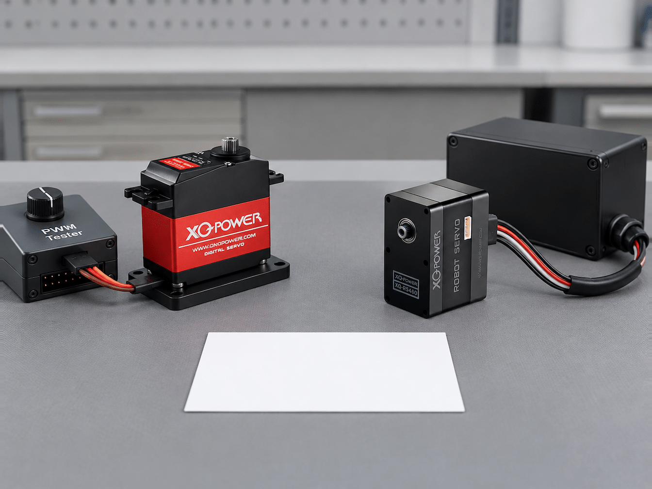
The answer depends on the required measurement and the complete servo design.
| Selection factor | Potentiometer feedback | Magnetic feedback |
|---|---|---|
| Contact wear | Has a mechanical electrical contact that can wear over time | Uses non-contact sensing, so there is no wiper wear at the sensing interface |
| Center calibration | Can be calibrated to a defined electrical and mechanical center | Requires correct magnet alignment and sensor zero calibration |
| Mechanical sensitivity | Sensor coupling, gears, backlash, and output support still affect the result | Magnet position, air gap, concentricity, and shaft runout can affect the result |
| Temperature behavior | Resistive track, controller reference, housing, and mechanical parts can change with temperature | Sensor, magnet, electronics, and mechanical spacing can change with temperature |
| Vibration and shock | Contact stability and mechanical coupling must be maintained | Magnet retention, alignment, and calibration must be maintained |
| Best comparison method | Measure actual center error and repeatability after cycling | Measure the same metrics under the same mechanical and thermal conditions |
For an RC helicopter, compare the two complete servos using the same horn, linkage geometry, supply voltage, load, control signal, temperature, and test duration. A sensor-level comparison without the same gear train and mechanical interface can produce the wrong conclusion.
Why can the mechanical system dominate center stability?
The position sensor only reports what it detects. If the sensor is located upstream of backlash, flex, or compliance, the reported position may not equal the position of the helicopter control surface.
Mechanical factors that can move the apparent center include:
- Gear clearance between the motor and output shaft
- Spline or horn fit
- Loose retaining screw or clamp
- Flexible servo arm or linkage
- Ball-link clearance
- Mount flex in the helicopter frame
- Bearing clearance or output-shaft radial movement
- Misalignment that creates side loading
- Temperature-dependent expansion of the frame or linkage
- Vibration-induced movement at the attachment points
The servo mounting and spline guide explains why output-interface fit, alignment, load direction, and structural support must be evaluated as one assembly. A sensor upgrade cannot compensate for a loose horn, worn gear train, or flexible linkage.
How does the control algorithm affect center performance?
The controller converts the position error into motor command. Its behavior affects how quickly the servo corrects center error and whether it oscillates around the target.
Important control variables include:
- Error scaling and proportional gain
- Dead-band implementation
- Integral correction and long-term drift compensation
- Derivative or damping behavior
- Motor drive frequency and update rate
- Position sampling rate and filtering
- Saturation and current limiting
- Startup calibration and zero-reference handling
- Direction and travel-limit mapping
A narrow dead band can reduce visible residual error, but excessive gain may create hunting, audible buzzing, or thermal loading. A wider dead band can reduce chatter while allowing more center error. The correct setting depends on the mechanics, sensor noise, load, and control objective.
The S3240M page lists a 3 μsec dead band. That is useful for understanding the product’s control specification, but it is not equivalent to a 3 μsec-to-angle conversion or a claim that the servo has a particular center accuracy. Pulse width, mechanical travel, gear ratio, and the controller’s internal mapping must all be considered.
How can a magnetic sensor show center error?
A magnetic sensor can show center error when the magnet and sensing element are not arranged around the intended centerline. Common causes include:
- Magnet eccentricity relative to the shaft
- Incorrect sensor-to-magnet distance
- Tilt between the magnet axis and sensing plane
- Uneven magnetic-field distribution
- Magnet displacement under vibration or shock
- Temperature-dependent changes in magnet strength or mechanical spacing
- Incorrect electrical zero calibration
- Nonlinear angle conversion in firmware
- Signal filtering that introduces a phase or settling effect
The error may be small at one angle and larger at another. A center-only check can therefore miss a broader linearity or repeatability problem. Map the output through the operating range and approach center from both directions.
How can a potentiometer show center drift?
A potentiometer can show center drift or repeatability variation when the contact path, sensor coupling, or mechanical transmission changes. Possible causes include:
- Wiper and resistive-track wear
- Contamination or oxidation
- Contact pressure variation
- Mechanical vibration at the sensor coupling
- Gear or bearing clearance
- Thermal expansion of the sensor or case
- Electrical reference variation
- Long-duration cycling beyond the intended duty cycle
A potentiometer’s contact-based design is not automatically a weakness in every application. For a servo that is correctly designed, calibrated, and operated within its intended environment, it can provide stable feedback. The design team should still measure the change in center error after the expected cycle count and environmental exposure.
What should RC helicopter engineers measure?
A practical comparison should use measurable acceptance criteria instead of a sensor label. Test the servo in the helicopter mechanism or in a fixture that reproduces its load and linkage geometry.
1. Static center repeatability
Command the same center pulse repeatedly. Record the output angle with a calibrated measurement device. Report the mean, range, and standard deviation, and identify whether the final position differs depending on approach direction.
2. Bidirectional hysteresis
Approach center from positive and negative travel. Measure the final output position after the servo settles. The difference indicates a combination of backlash, friction, compliance, and controller behavior.

3. Temperature cycle
Repeat the center and travel tests at the minimum, room, and maximum temperatures relevant to the application. Record the sensor output, servo case temperature, supply voltage, current, and mechanical center at each condition.
4. Vibration and shock exposure
Use the expected rotor vibration and mechanical mounting conditions where possible. Check the horn fastener, spline engagement, linkage, frame attachment, sensor calibration, and center position after exposure.
5. Long-duration cycling
Run the expected cyclic or tail-control profile for a defined number of cycles. Measure center error at intervals and inspect the gear train, output interface, linkage, and sensor behavior at the end of the test.
6. Supply-voltage sensitivity
Repeat the center test across the servo’s specified voltage points. A supply drop can change motor torque, control margin, and dynamic behavior. Do not compare two sensor technologies using different voltage conditions.
7. Load and direction reversal
Apply the actual aerodynamic or mechanical load, then reverse direction around center. Record the command-to-position relationship, overshoot, settling, current, and residual error.
How should a servo be selected for cyclic, tail, or collective control?
Define the control role before selecting a sensor or model:
- Cyclic control: Requires consistent small-angle corrections, low unwanted backlash, predictable response, and stable linkage geometry.
- Tail control: May require rapid reversals, low hysteresis, good settling, and stable center under vibration.
- Collective or pitch control: May impose higher sustained load and requires careful mechanical support, torque sizing, and thermal evaluation.
For all three roles, sensor type is only one selection variable. The servo’s torque margin, speed under load, gear train, output spline, controller behavior, mechanical installation, and environmental conditions matter at least as much as the sensor principle.
The XQ-POWER Technical Guide covers related topics including servo sizing, communication, encoder types, environmental protection, and thermal management. For a product with a published potentiometer specification, see the S3240M product page.
What information is needed to compare a magnetic-sensor variant?
Request the exact model and variant before making a product-level comparison. The required information includes:
- Sensor type and sensing element
- Sensor position relative to the output shaft
- Resolution and angle range
- Center calibration method
- Repeatability and hysteresis test conditions
- Temperature drift data
- Vibration and shock conditions
- Gear, bearing, spline, and output-shaft configuration
- Controller update rate, dead band, and filtering
- Supply voltage and load used for the test
- Expected cycle count and maintenance interval
The accessible XQ-POWER pages used for this article identify the S3240M’s analog potentiometer but do not identify a specific magnetic-sensor product with a comparable center-stability dataset. Engineering confirmation is required before stating that a particular magnetic variant has a specified accuracy or repeatability advantage.
Direct answer for RC helicopter applications
A potentiometer version is not automatically more stable at center than a magnetic-sensor version. The S3240M provides a published example of an XQ-POWER PWM servo with an analog potentiometer, 3 μsec dead band, metal gears, and dual ball bearings. A magnetic sensor can eliminate sliding-contact wear, but its center behavior depends on magnet alignment, field distribution, temperature, calibration, and control software.
Potentiometer vs Magnetic Servo Center Stability FAQ
No. Center stability depends on the sensor, control algorithm, gear backlash, output connection, linkage, vibration, temperature, calibration, and load. A well-designed potentiometer servo can be stable, and a well-designed magnetic-sensor servo can also be stable. Compare measured center error and repeatability under the same conditions.
The S3240M product page identifies a high-precision analog potentiometer and PWM control. It also lists a 3 μsec dead band. These specifications do not by themselves define the complete center-accuracy or repeatability of the servo in an RC helicopter.
No. Non-contact sensing removes sliding electrical contact wear, but center behavior can still be affected by magnet alignment, magnetic-field distribution, temperature, calibration, shaft runout, vibration, and control software.
Yes. The wiper and resistive track can change with long-term cycling, contamination, vibration, or contact stress. Gear backlash, output-horn fit, and linkage wear can also affect center position even when the potentiometer itself remains functional.
Common causes include gear backlash, spline or horn looseness, linkage clearance, frame flex, bearing clearance, output-shaft side loading, misalignment, temperature expansion, supply-voltage changes, vibration, and control-loop settings.
Measure static repeatability, approach-direction hysteresis, temperature drift, vibration response, long-duration cycling, voltage sensitivity, and loaded direction reversals. Record output angle, current, temperature, supply voltage, settling behavior, and mechanical condition at each stage.
Need help selecting a feedback configuration?
Send the application role—cyclic, tail, collective, robotic joint, or other mechanism—together with the required torque, speed, voltage, travel, duty cycle, vibration, temperature, linkage geometry, and center-stability target to the XQ-POWER engineering team. The team can discuss the appropriate model, sample testing, and OEM/ODM options for a defined motion-control requirement.