
A multi-servo system needs more than a power supply with the correct nominal voltage. When several actuators accelerate, reverse, or hold load at the same time, the distribution network must deliver the required current while keeping the voltage at each servo within the selected model’s specified range.
The same principle applies to response speed. A product page may list a movement speed such as 0.07 sec/60° or 0.14 sec/60°, but the complete system response also includes controller processing, communication transfer, bus scheduling, servo processing, motor acceleration, load inertia, and settling. The reliable engineering method is to measure the voltage and timing at the servo and mechanism—not only at the power supply and software command.
What should be checked first in a multi-servo installation?
Before selecting a supply or wiring layout, define the complete system:
- Number of servos and exact model variants
- Model-specific operating-voltage range
- Continuous and transient current requirement
- Torque, speed, acceleration, and duty cycle for each axis
- Whether axes move simultaneously or sequentially
- Cable length, conductor size, connectors, and distribution points
- Control interface: PWM, RS485, CAN, or another documented variant
- Mechanical load, inertia, friction, and required settling window
- Ambient temperature and enclosure conditions
- Voltage and response limits that determine pass or fail
The nominal supply voltage alone is not enough. Two installations can use the same voltage source but behave differently because of cable resistance, connector contact, distribution topology, battery condition, or the number of axes active at one time.
How much power does a multi-servo system need?
Power planning should distinguish at least three conditions:
- Quiescent or no-load demand: servos powered but not producing significant motion or holding torque.
- Normal operating demand: the current needed during the expected motion cycle.
- Transient demand: short current peaks during acceleration, reversal, rapid correction, or high-load holding.
A simplified first estimate is:
Total system current = sum of the current required by the active servo axes and control electronics under the defined condition
This is only a starting point. The final power design should use the model-specific current data, load profile, duty cycle, and measured behavior. A supply that appears adequate during single-axis movement may experience voltage sag when several axes accelerate together.
Do not size the supply only from the servo’s no-load current. The XQ-POWER product pages show why model and operating condition matter. For example, the S9150D page lists a 10.0 A stall-current point at 16.8 V, while the S9450D page lists stall-current points of 18 A at 24 V, 21 A at 28 V, and 22.5 A at 30 V. These are not universal continuous-current requirements, but they show why the selected model, voltage, load, and duty cycle must be considered together.
Why the voltage at the servo can be lower than the supply voltage
The power supply output is measured at one location. The servo operates at another location. Between them are conductors, connectors, fuses, switches, distribution blocks, and possibly several branches.
Under load, each element can contribute resistance. The resulting voltage at the servo terminals can be lower than the nominal source voltage, especially when:
- Several axes share one cable or connector path.
- A long cable feeds a high-current actuator.
- A connector is undersized, loose, oxidized, or poorly crimped.
- A branch distribution point carries simultaneous acceleration current.
- A battery or regulator output changes under transient load.
- The return path is shared with noisy or high-current equipment.
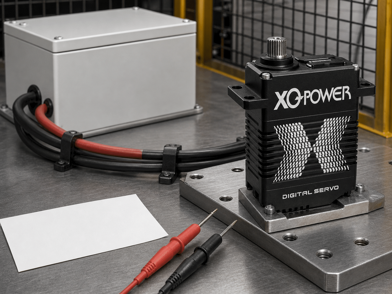
A voltage drop can reduce available torque, change movement speed, cause resets, or make one axis behave differently from another. The correct measurement is voltage directly at the actuator connector while the actual system is moving and holding load.
How should a multi-servo power distribution be arranged?
The exact architecture depends on the machine, but the design review should consider:
Use the exact voltage range for each model
Do not assume that all XQ-POWER servos accept one common range. Published examples include the BLS8125D at 6.0–8.4 V, the S9150D at 8.4–16.8 V, and the RS460 with a native 12 V input. The S9450D and S9750D pages list 24–30 V operating ranges. A mixed-model installation may therefore require separate regulated branches or an approved common-voltage strategy.
Size conductors and connectors for the real load
Select conductor size, connector rating, contact arrangement, and protective devices for the expected continuous and transient conditions. Do not choose these parts solely from the average current of a single servo.
Keep high-current paths short where practical
Longer paths increase the opportunity for voltage drop. The farthest actuator and the actuator with the highest expected load deserve particular attention during testing.
Separate power planning from communication planning
An RS485 or CAN bus can reduce signal wiring complexity, but it does not guarantee uniform voltage at every actuator. Signal wiring and power distribution must both be designed and tested.
Provide measurement points
Include safe access points for measuring source voltage, branch voltage, and voltage at critical servo connectors during commissioning. A system that cannot be measured is difficult to diagnose when several axes move at once.
How does model selection affect a multi-servo power plan?
The RS460 Modbus RS485 smart robot servo is listed with a 58 kg·cm torque point at 12 V, 0.14 sec/60° speed at 12 V, and feedback fields including position, temperature, speed, voltage, and current. Its page also identifies Modbus RS485 communication and up to 254 daisy-chained nodes.
This makes the RS460 relevant to distributed motion-control discussions, but the node count does not define the power capacity of the system. The supply and distribution must still be designed for the number of active axes, their load, and their simultaneous current demand.
The BLS8125D brushless servo is listed with 6.0–8.4 V operation, 25 kg·cm torque at 8.4 V, and 0.07 sec/60° speed at 8.4 V. It may be suitable for a different power domain from a 24–30 V industrial actuator. A system integrator should not connect both models to the same unregulated supply without confirming compatibility and the complete power architecture.
The S9150D industrial brushless servo is listed with 8.4–16.8 V operation, 180 kg·cm peak stall torque at 16.8 V, and 0.14 sec/60° speed at 16.8 V. Its high current and torque class require a different supply and wiring review from a compact 25 kg·cm actuator.
What should be done when product pages show conflicting data?
A system design should use the current model-specific datasheet or inspection specification, not a conflicting web-page value selected for convenience. This is especially important when the same product page contains inconsistent voltage or speed labels.
For example, the accessible RS8125D page lists 6.0–8.4 V and 0.07 sec/60° at 8.4 V in one specification table, while other page text refers to 24 V and a 12.0–24 V range. That inconsistency should be resolved with the current RS8125D datasheet and engineering team before the model is connected to a power system or used in a performance comparison.
This is not a reason to estimate a “safe” range. It is a reason to pause that model’s integration until the exact variant and documentation are confirmed.
How does communication affect coordinated response?
A multi-axis system may use PWM, RS485, CAN, or another documented interface. The interface affects how commands are transmitted and scheduled, but it does not remove the mechanical and power delays.
For PWM, separate channel timing and controller update behavior affect when each axis receives its command. For a serial bus, frame length, baud rate, polling, node addressing, and bus scheduling affect when each actuator receives an update. For CAN, message priority and bus traffic affect timing according to the documented network design.
The XQ-POWER Technical Guide identifies protocol selection and communication integration as part of servo engineering. The exact timing must be measured with the selected controller, firmware, cable arrangement, bus load, and number of axes.
Do not describe a product as “instant response” simply because its no-load movement-speed figure is fast. A fast actuator can still have a longer system response if the command is delayed by controller processing, bus traffic, voltage sag, mechanical inertia, or settling requirements.
How should end-to-end response time be measured?
Define the start and end points before collecting a number. A useful test can include the following stages:
- Command generation: the controller creates the target position or motion command.
- Transmission: the command passes through the selected output channel, cable, transceiver, and bus schedule.
- Servo reception: the actuator recognizes the command and updates its control loop.
- Mechanical movement: the motor accelerates the real load.
- Settling: the output enters the required position window and stays there.
The measured result should state whether it represents:
- Controller-to-signal-output delay
- Signal-reception delay
- Output-shaft movement time
- Load movement time
- Time to enter a defined position window
- Time to settle within a specified error band
A product value such as 0.07 sec/60° is not automatically the same as controller-to-settled-position time. The servo voltage and response guide discusses the difference between model-specific movement speed and complete system latency.
What test equipment and signals are useful?
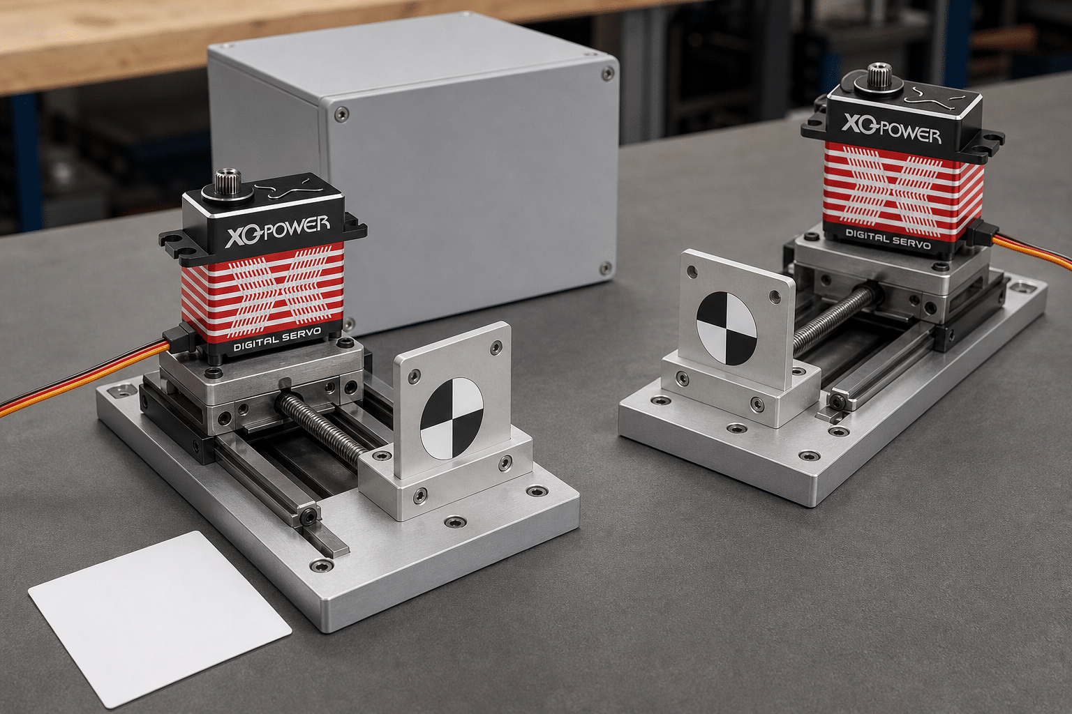
The equipment depends on the required accuracy, but a commissioning plan may include:
- A regulated supply or battery emulator sized for the expected load
- Voltage measurement at the source and at selected servo terminals
- Current measurement on the main branch and critical axes
- A controller or bus monitor with timestamp capability
- An oscilloscope or logic analyzer for command timing where appropriate
- A position sensor, encoder output, or camera-based measurement for the mechanism
- Temperature measurement on the servo case and power-distribution components
- A guarded fixture with the real load or a controlled load equivalent
Use the same voltage, load, acceleration, and number of active axes when comparing two configurations. Otherwise, the measured response numbers do not represent the same test condition.
How should simultaneous acceleration and holding be tested?
A multi-servo test should include the conditions that create the highest combined demand:
- All axes accelerating together
- Several axes reversing direction together
- One high-load axis holding while other axes move
- Repeated start-stop cycles
- The longest cable branch under the highest expected load
- Low battery or supply tolerance conditions when relevant
- Maximum expected ambient temperature
- Communication traffic representative of production use
Record source voltage, far-end voltage, branch current, servo current where available, position response, temperature, and any reset or communication error. A single-axis unloaded test cannot prove multi-axis stability.
How can voltage instability be separated from communication latency?
Change one condition at a time and record the result:
- Run one servo with a short power cable.
- Run the same servo with the intended cable and load.
- Add the other axes without changing the command timing.
- Monitor voltage at the critical servo during the event.
- Compare the response with stable voltage and with the observed voltage dip.
- Check communication timestamps separately from mechanical position.
If the command arrives on time but the mechanism moves late or inconsistently while voltage falls, investigate power delivery and load conditions. If the voltage remains stable but command timestamps vary, investigate controller scheduling, bus traffic, or protocol configuration. The two problems can also occur together.
What design data should be sent to XQ-POWER?
For a multi-servo selection or OEM/ODM review, provide:
- Exact servo models and variants
- Quantity of each model
- Intended supply voltage and tolerance
- Continuous and peak torque per axis
- Simultaneous-motion sequence
- Cable length, conductor size, connector, and distribution layout
- Controller and protocol details
- Required response and settling limits
- Mechanical load, inertia, acceleration, and duty cycle
- Ambient temperature and enclosure conditions
- Voltage and current measurements from the prototype
This information allows the XQ-POWER engineering team to review the real system rather than applying one generic “wide-voltage” or “fast-response” statement to every model.
For application-specific selection, use the XQ-POWER contact page.
Practical checklist for a stable multi-servo system
Before moving to production, confirm that:
- Every actuator is connected within its own specified voltage range.
- Voltage is measured at the servo terminals under simultaneous load.
- The supply and distribution support both continuous and transient demand.
- Cable, connectors, branches, and protective devices are selected for the load.
- Communication timing is tested with the intended number of nodes and traffic.
- Response time is defined from command generation to stable mechanical position.
- The test includes acceleration, reversal, holding, and repeated cycles.
- Position, current, temperature, voltage, and communication errors are recorded.
- Any inconsistent product-page specification has been resolved from the current datasheet.
- The selected configuration has passed a guarded test with the real mechanism.
Multi-Servo Power Supply and Response Time FAQ
Start with the exact model-specific voltage range, then size the supply and distribution for the combined continuous and transient demand of the active axes. Check cable, connector, branch, and return-path voltage drop, and measure voltage at the servos while they accelerate and hold the real load.
Possible causes include supply voltage sag, insufficient transient capacity, cable or connector resistance, shared distribution paths, communication scheduling, controller timing, mechanical load, or thermal conditions. Measure voltage and command timing at the same event instead of assuming that the servo itself is the only cause.
Not necessarily. Cable resistance, connectors, fuses, switches, distribution blocks, and shared branches can reduce the voltage under load. The relevant value for the actuator is the voltage measured at its connector during the actual multi-axis motion.
No. RS485 can simplify command and feedback wiring, but it does not replace power-distribution design. The bus architecture and the power network are separate engineering concerns. Both communication timing and terminal voltage must be tested.
No. It is a model- and condition-specific movement-speed figure. Complete response may also include controller delay, bus transfer, servo processing, motor acceleration, load inertia, mechanical compliance, and settling. Define the start and end points of the required measurement before comparing systems.
Confirm the exact model and variant, operating-voltage range, torque and speed test conditions, current data, control interface, feedback functions, cable and connector requirements, duty cycle, and any conflicting values in the product documentation. Resolve inconsistencies with the current datasheet or engineering team before integration.
Need help planning multi-servo power and response testing?
Share the model list, quantity, voltage, torque, cable layout, controller protocol, simultaneous-motion sequence, response target, and prototype measurements with the XQ-POWER engineering team. The team can review a standard multi-axis configuration, sample test, or OEM/ODM motion-control requirement.