
Direct answer: XQ-POWER servo gears do not automatically chip or fracture when a robot jumps or lands. A correctly selected high-torque robot servo can handle a defined transient load when the peak torque, impact duration, repetition rate, reflected inertia, and mechanical structure remain within the validated design envelope. However, a rigid impact far beyond the design torque—or repeated high-frequency overload—can cause tooth fatigue, deformation, chipping, or fracture in any metal gear train.
For a dynamic robot joint, the right question is not simply “How much rated torque does the servo have?” Engineers must determine how much impact energy reaches the output gear during the landing event, how quickly the energy is stopped, how often the event repeats, and whether an elastic foot, damper, compliant linkage, or external bearing changes the load path. XQ-POWER’s high-torque industrial and robot-oriented servo solutions can be evaluated for these applications, but final reliability must be confirmed with the actual robot geometry and duty cycle.
At-a-Glance Landing-Impact Takeaways
- A jump landing creates a dynamic torque event, not just a static payload load.
- Metal gears improve mechanical load capability but do not make a servo immune to excessive shock.
- Peak torque, impact duration, impact frequency, reflected inertia, and joint angle all affect gear stress.
- A short, rigid collision can create a higher peak load than a controlled landing with compliant contact.
- Elastic feet, dampers, flexible couplings, and controlled acceleration can reduce the energy transmitted to the gear train.
- Output bearing support, shaft alignment, housing stiffness, and fastener retention influence tooth contact during impact.
- A stall-torque value should not be treated as a guaranteed repeated-impact rating.
- Validate the assembled joint with the real mass, speed, payload, landing condition, and temperature.
Why Does a Robot Landing Create a High Gear Load?
A landing converts the robot’s downward motion into a rapidly changing reaction force. The ground force travels through the foot, lower link, joint bracket, output shaft, gear train, housing, and frame. If the stopping distance is short, the force rises quickly.
The main factors are:
- Effective moving mass: The joint may experience the mass of the leg, body, payload, and downstream structure.
- Landing velocity: Kinetic energy increases with the square of velocity, so a small increase in landing speed can produce a much larger energy event.
- Stopping distance: A compliant foot or damper can increase the distance over which the robot decelerates.
- Lever arm: The ground reaction force creates a joint moment based on its distance from the joint axis.
- Contact stiffness: A hard surface and rigid linkage transfer energy faster than a compliant contact system.
- Joint configuration: The same ground force can produce different torque at different leg angles.
- Impact repetition: A gear train may survive one event but degrade under thousands of repeated landings.
A smooth bench test may therefore show normal operation while a jump or collision exposes a much higher transient load. The damaging condition is often the maximum torque at the tooth contact, not the average torque over the motion cycle.
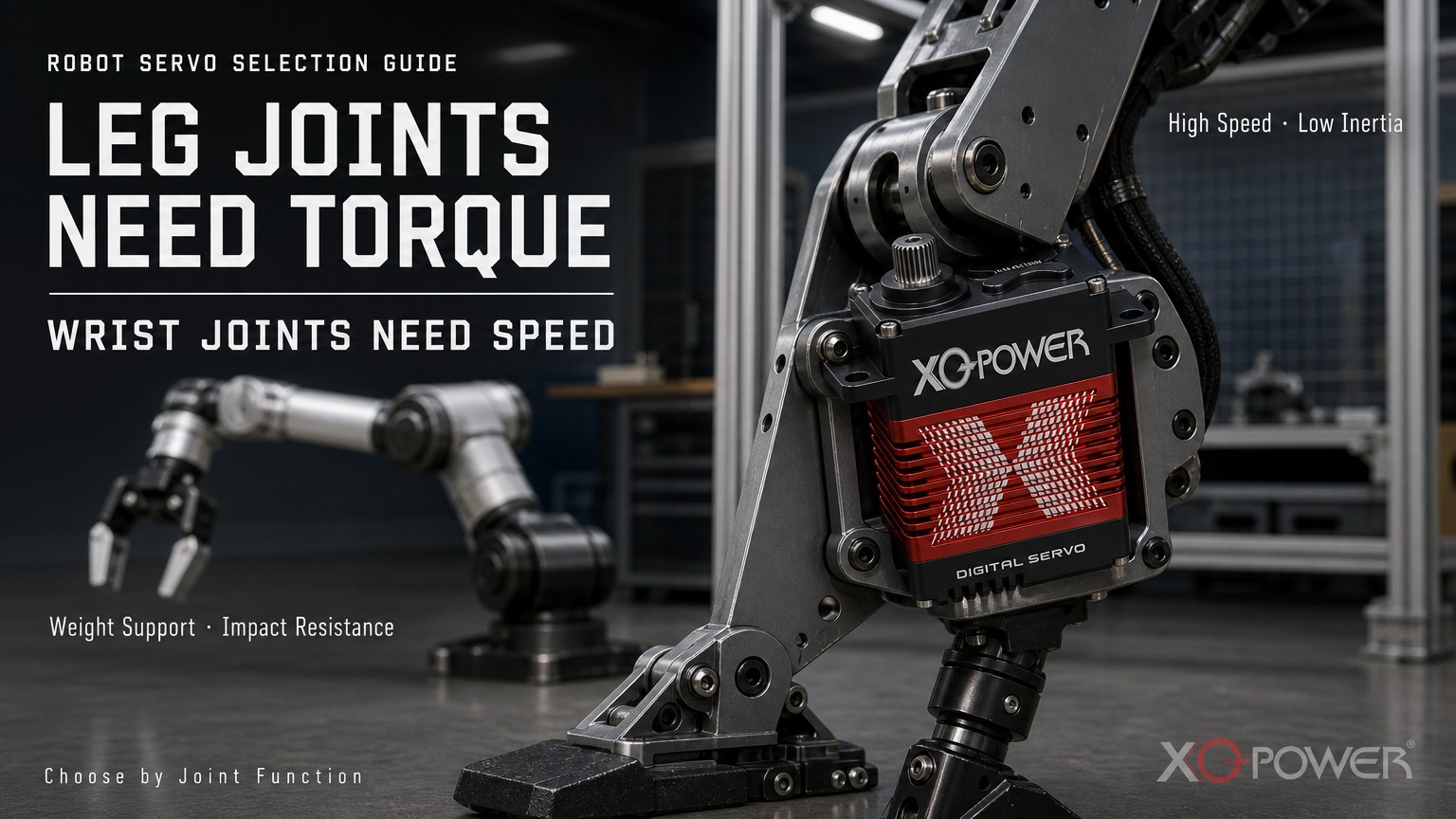
What Is the Difference Between Normal Load, Peak Torque, and Impact Torque?
Robotic joint selection should separate several operating conditions:
- Normal operating torque: Torque required during ordinary movement.
- Holding torque: Torque required to maintain the joint position against gravity or an external force.
- Acceleration torque: Torque required to accelerate the links, payload, and reflected inertia.
- Peak transient torque: Short-duration torque during a sudden movement, hard stop, or contact.
- Impact torque: Torque generated when a moving mass is rapidly decelerated by a landing or collision.
- Stall torque: Torque measured under a specified stalled or near-stalled test condition.
These values are not interchangeable. A servo may have a high stall-torque result but still require additional mechanical protection for repeated impacts. Conversely, a joint with moderate average torque may experience a severe landing spike if its stopping distance is too short.
XQ-POWER’s S9750D product page provides a useful example of why voltage and test conditions must be stated. Its inspection specification records peak stall torque values of 850 kg·cm at 24 V, 920 kg·cm at 28 V, and 980 kg·cm at 30 V. Those are product-specific peak stall results. They should not be interpreted as a universal repeated-landing rating or a promise that the servo will survive any collision.
See the XQ-S9750D industrial servo reference and confirm the applicable load, duty-cycle, mechanical-interface, and impact limits for the exact variant.
Can Metal Gears Prevent Tooth Fracture?
High-strength metal gears can improve the mechanical load capability of a servo compared with a gear system not designed for the same load class. XQ-POWER’s high-torque industrial product information identifies steel gear structures, metal cases, and bearing-supported output systems in its high-output servo range. These design elements are relevant when a robot joint must transmit a substantial mechanical moment.
However, a metal gear is not an unlimited shock absorber. Tooth failure risk still depends on:
- Tooth geometry and root thickness;
- Material and heat treatment;
- Surface finish and lubrication;
- Gear reduction arrangement;
- Number of teeth sharing the load;
- Backlash and direction reversal;
- Bearing support and shaft deflection;
- Housing stiffness and alignment;
- Temperature and repeated-cycle history;
- Peak impact energy and contact position.
A gear may fail through tooth-root bending, tooth-edge chipping, surface pitting, plastic deformation, or fatigue crack growth. A landing that does not produce immediate fracture may still increase backlash or damage the tooth surface, causing a later failure under a smaller load.
The XQ-POWER high-torque servo category is a starting point for identifying candidate industrial models. The gear material and product class must then be matched with the actual robot impact condition.
How Can Engineers Estimate Landing Impact Torque?
A first-order energy estimate is:
E_impact = 1/2 × m_effective × v_landing²
where m_effective is the effective moving mass and v_landing is the velocity at contact.
If the system stops over an estimated distance d_stop, the average stopping force can be approximated as:
F_average ≈ E_impact / d_stop
The corresponding joint moment is approximately:
T_impact ≈ F_impact × r_joint
where r_joint is the perpendicular distance from the joint axis to the force line.
These equations help engineers compare design options, but they do not predict the exact peak force. Real systems have non-linear springs, damping, structural flex, friction, ground compliance, and changing contact geometry. For high-dynamic robots, use force plates, load cells, torque sensors, accelerometers, or other appropriate instrumentation when possible.
The robotic-arm servo selection and reliability guide provides related guidance on dynamic torque, gear loading, encoder feedback, and thermal conditions.
Which Mechanical Features Reduce Shock Transmission?
Elastic feet and compliant contact
An elastic foot can increase the stopping distance and spread the landing event over a longer time. This can reduce peak force at the joint, but it may also introduce rebound, compliance error, or control delay. Select the stiffness and travel for the actual mass, speed, and landing frequency.
Dampers and shock absorbers
A damper converts part of the impact energy into heat and controls rebound. A damper that is too soft may permit excessive travel or bottoming; a damper that is too stiff may transfer a larger force into the servo.
Flexible couplings and compliant joints
Controlled torsional compliance can reduce the impulse caused by a sudden reversal or contact. The coupling must still maintain alignment and should not create uncontrolled backlash that harms position control.
Motion-profile control
Reducing acceleration, braking rate, and reversal aggressiveness can reduce the energy present at contact. Current limits and trajectory shaping can support the mechanical protection strategy, but software limits cannot compensate for a joint that is fundamentally undersized.
External bearing support
If the output shaft receives radial or bending load from the leg linkage, an external bearing can carry the structural load. This helps the servo transmit torque without using the output shaft as an unintended structural axle.
How Do Alignment and Backlash Affect Landing Damage?
A landing can amplify small mechanical weaknesses. If the mounting bracket twists, the output shaft bends, or the linkage is misaligned, the gear teeth may contact near one edge rather than across the intended working surface. Edge loading increases local stress.
Before dynamic testing, check:
- Mounting-face flatness;
- Fastener preload and retention;
- Shaft and linkage alignment;
- External bearing position;
- Output play and backlash;
- Housing stiffness;
- Tooth contact pattern;
- Structural clearance at full travel;
- Cable routing and connector strain.
Backlash also matters during foot contact. When the joint reverses direction, clearance can allow the gears to engage with a small impact before the full load is transmitted. Excessive clearance may increase noise, position error, and tooth-edge stress.
For installation and system integration reference, use the XQ-POWER Technical Guide together with the selected model’s mechanical drawing and engineering confirmation.
What Does Repeated High-Frequency Overload Do to the Gears?
Repeated overload can cause cumulative damage even when no single event breaks a tooth. Possible progression includes:
- Small surface marks or polishing at the tooth contact;
- Increasing backlash or output play;
- Periodic vibration or clicking at a repeatable angle;
- Tooth-edge chipping or local deformation;
- Crack growth at a tooth root;
- Sudden loss of position or output torque.
Temperature also influences fatigue. Repeated high current and high holding torque can heat the motor, driver, lubricant, housing, and gear train. A hot joint may have different clearance and friction than a cold joint. For this reason, repeated landing tests should include the temperature condition expected in the mission.
A robot-dog or humanoid platform may appear to operate normally during a short demonstration but experience very different gear stress over a long gait cycle. XQ-POWER describes robot-dog solutions as requiring dynamic joints, shock absorption, terrain adaptation, and gait stabilization. Those requirements should be translated into a measured cycle profile rather than a single peak load estimate.
How Should a High-Dynamic Robot Joint Be Validated?
A staged test plan is more informative than a single hard landing.
Baseline inspection
Record backlash, output-shaft play, bearing noise, no-load current, position repeatability, and gear condition before testing.
Static holding test
Apply the expected standing or holding load at representative joint angles. Monitor current, temperature, position error, and visible deflection.
Controlled dynamic test
Run the intended acceleration, deceleration, reversal, and gait profile at increasing load levels. Record current, temperature, vibration, position, and external force.
Landing-impact test
Define the landing velocity, effective mass, stopping distance, contact surface, joint angle, number of events, and interval. Use instrumentation when possible and protect personnel from unexpected mechanical release.
Repeated-cycle test
Repeat the landing or impact event for the expected mission count plus an engineering margin. Inspect for increasing backlash, tooth marks, noise, position error, bearing play, and shaft looseness.
Post-test teardown
Inspect tooth roots, tooth flanks, gear edges, shafts, bearings, fasteners, housing interfaces, and lubrication condition. Compare the results with the baseline record.
XQ-POWER’s Solutions page covers industrial robotic arms, robot dogs, humanoid robots, AGVs, and other demanding motion-control applications. Each platform needs a validation plan based on its own geometry and impact energy.
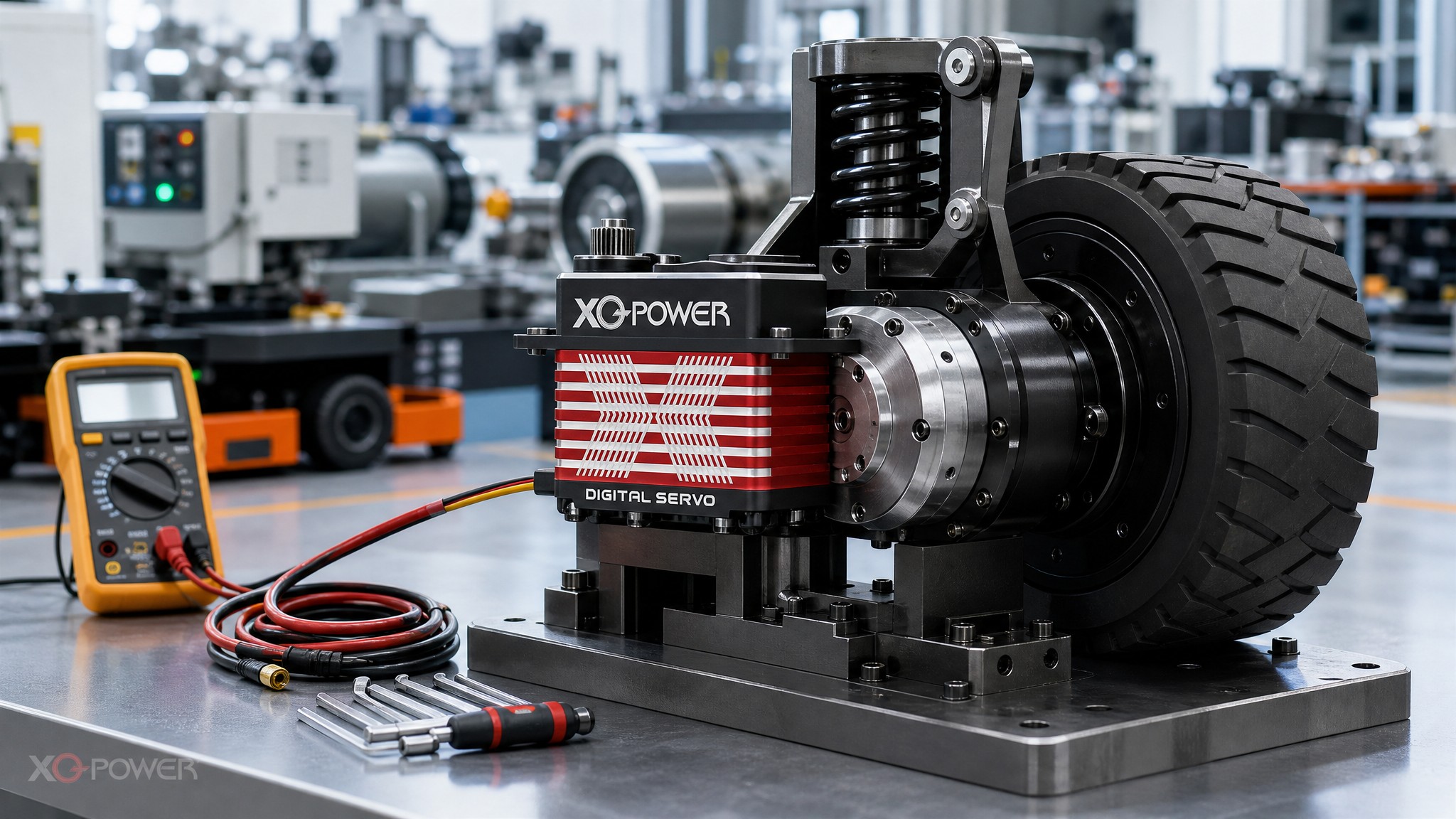
How Can Encoder Feedback Help Detect Shock Damage?
Encoder feedback cannot prevent every mechanical failure, but it can reveal changes after a landing event. Monitor:
- Position error at a known command;
- Settling time;
- Overshoot and oscillation;
- Dead zone during direction reversal;
- Current needed to hold position;
- Vibration synchronized with output angle;
- Difference between commanded and externally measured joint angle.
A damaged tooth may create a repeatable position error or vibration at a particular output angle. Increased backlash may appear as a larger dead zone when the direction changes. A magnetic encoder can support closed-loop monitoring, but it cannot remove mechanical play between the feedback point and the final foot or tool.
How Should XQ-POWER Servo Models Be Selected for Jumping Robots?
Use an application-first selection process:
- Define the robot mass, payload, joint axis, foot contact location, and landing velocity.
- Estimate static, holding, dynamic, and impact torque separately.
- Include reflected inertia, lever arms, ground reaction force, and stopping distance.
- Select a servo with appropriate peak and continuous torque margin.
- Confirm gear structure, output bearing support, mounting, alignment, and allowable external loads.
- Add an elastic foot, damper, flexible coupling, or other mechanical buffer where needed.
- Match the voltage, current capacity, feedback, and communication interface.
- Run static, dynamic, landing, repeated-cycle, thermal, and post-test inspections.
For high-inertia robot joints, review the available XQ-POWER industrial and high-torque servo solutions and then confirm the exact model against the joint’s measured duty cycle and shock profile.
Frequently Asked Questions About Robot Landing Shock Loads
No. A properly selected servo does not automatically suffer tooth fracture during a normal jump or landing. Risk depends on peak torque, impact duration, impact frequency, inertia, alignment, mechanical compliance, and whether the load remains within the validated design envelope.
Metal gears can support demanding mechanical loads, but they are not immune to excessive impact. A rigid collision or repeated overload can cause fatigue, deformation, chipping, or tooth fracture if the transmitted load exceeds the gear system’s limit.
No. Stall torque is measured under a specified test condition. Landing-impact capacity also depends on impact energy, stopping distance, joint angle, repetition count, gear support, bearing alignment, temperature, and the complete mechanical structure.
It can reduce peak transmitted force by increasing stopping distance and absorbing part of the impact energy. The compliant element must be tuned to the robot mass, landing speed, stroke, rebound, and cycle frequency.
Check tooth flanks and roots, backlash, output-shaft play, bearing noise, mounting fasteners, linkage alignment, current, position repeatability, vibration, and any error that repeats at a particular joint angle.
Yes. Provide the robot mass, payload, joint geometry, peak and continuous torque, speed, landing condition, impact frequency, voltage, feedback, mounting, and duty cycle. XQ-POWER can review the suitable model or OEM/ODM path, subject to application-level validation.
Conclusion
XQ-POWER servo gears do not automatically break when a robot jumps or lands. With a suitable high-torque model, sufficient peak-load margin, correct mounting, controlled impact energy, and appropriate mechanical compliance, normal transient landings can be managed without immediate tooth fracture.
However, no metal gear train should be treated as immune to damage. A rigid collision far beyond the design torque or repeated high-frequency overload can lead to tooth fatigue, deformation, chipping, increased backlash, or fracture. The reliable engineering path is to measure the real impact condition, select by peak and continuous load, use mechanical buffering where needed, and validate the complete robot joint over its intended mission cycle.