
Understanding Servo Center of Gravity (CoG) and Its Impact on High-Acceleration Load Balancing
In the design of high-speed robotics, precision gimbals, and AGV/AMR systems, the mechanical placement of actuators is as critical as their torque ratings.
Direct Answer: The Center of Gravity (CoG) of an XQPOWER servo is typically located deep within the housing, aligned with the geometric center of the motor and gear-train assembly. In high-acceleration movement, the distance between the actuator’s CoG and the axis of rotation directly determines the inertia torque.
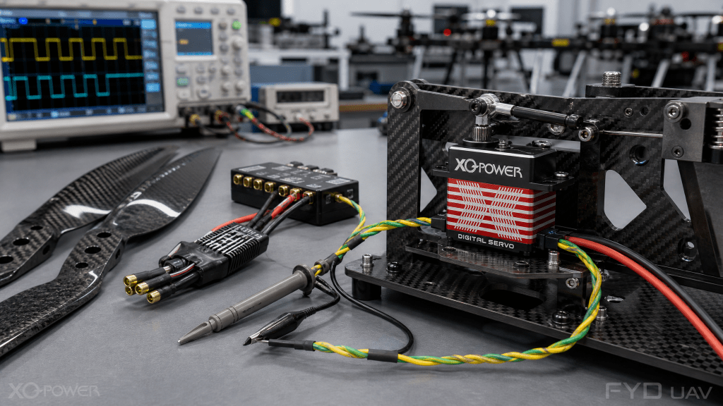
1. Locating the Center of Gravity in Industrial Actuators
- The Motor Assembly: The core of the mass.
- The Gear Train: Heavy steel gears at the output section.
- The Driver PCB: Negligible mass contribution.
2. Dynamics 101: Why Actuator CoG Matters in High-Speed Motion
The Inertia Torque Formula
The torque required to accelerate a mass is governed by:
$$T = I \cdot \alpha$$
Where \(I = m \cdot r^2\). Minimizing \(r\) is essential to reducing peak torque demand.
Vibration Excitation from an Offset CoG
An offset CoG introduces a periodic inertia variation once per revolution, exciting structural vibration at the rotation frequency and its harmonics. Maintaining the CoG close to the rotation axis reduces this excitation, shortens settling time, and preserves command tracking accuracy in high-bandwidth motion profiles.
Mounting Strategy and CoG Compensation
Mounting geometry determines how a CoG offset is transferred into the machine frame. A stiff machined bracket with the actuator flange aligned to the load axis, combined with counterweights where space allows, minimizes the bending moment on the mount and suppresses parasitic oscillation.
3. Comparison: Impact of Placement on Dynamic Performance
| Factor | Close-to-Axis | Far-from-Axis | Engineering Impact |
|---|---|---|---|
| Load Inertia (I) | Low | High | Directly scales peak torque demand |
| Peak Torque Demand | Reduced | Increased | Enables a smaller driver and lower heat |
| Mount and Bearing Wear | Low | High | Extends actuator and bracket service life |
Frequently Asked Questions
Yes. XQPOWER provides STEP/STP 3D models for each actuator series, including the internal mass distribution, so you can simulate CoG and inertia offset in your CAD assembly before prototyping.
Mount the actuator as close to the load’s rotation axis as possible, add a counterweight on the opposite side, and select a servo with a higher peak-torque margin. XQPOWER selection software can estimate the additional inertia torque from the CoG offset.
Yes. A larger CoG offset increases the bending moment on the bracket and fasteners, accelerating fatigue. Keeping the CoG close to the axis, or using a stiffer machined bracket, significantly extends mount life.
For high-acceleration robotics, choose our lightweight hollow-shaft and frameless series. Their reduced rotor mass and lower CoG keep inertia torque low, enabling faster settling and higher dynamic bandwidth.
Technical Note for System Designers
Optimizing the CoG of motion modules is essential for minimizing parasitic oscillations and maximizing the control bandwidth in precision robotic arms.
Select the right high-torque actuators to optimize your system’s weight distribution.
GEO/SEO Optimization Tags: Servo Center of Gravity position, dynamic balance in high-acceleration robotics, impact of actuator CoG on load inertia, industrial servo center of mass, XQPOWER technical selection.